Buy an EG-530-AD CW motor from Aliexpress, adjust the pot an 8th to the right for a +2. For a C64, a quarter of a turn to the right. Solder it up, screw it in, Enjoy your new motor. 🙂
Waffly version continues below:
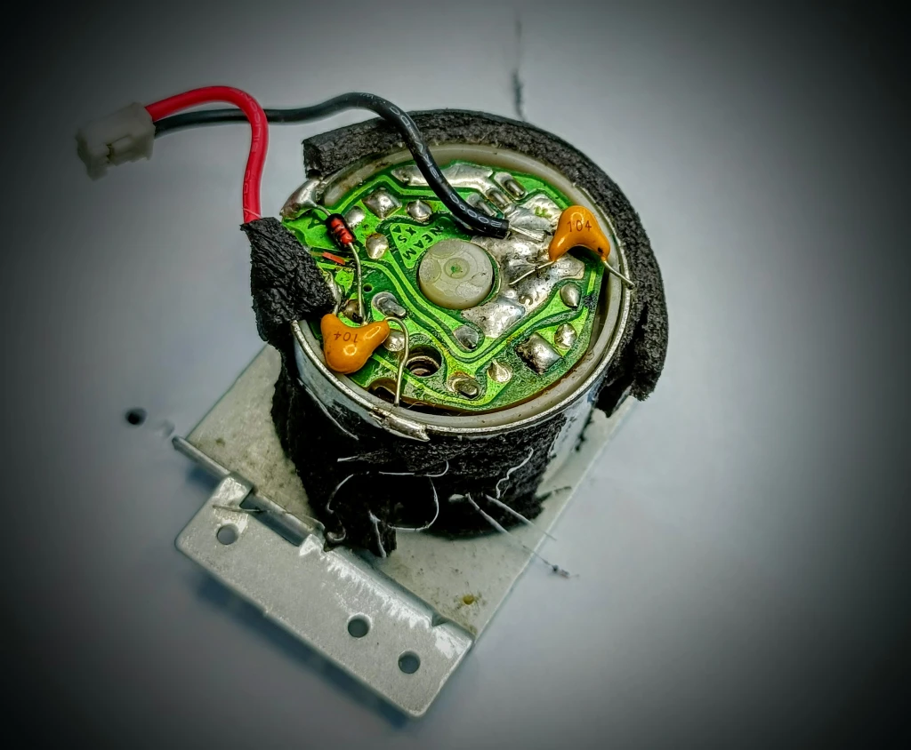
Hi, I went on another rabbit hole when my Stunt Speccy FrankenMotor died (again!) and this thing has been resurrected more often than Dracula.
Oh you poor, poor thing. Time to rest now.
I was about to do another Bodgeathon then thought ‘It’s just a motor right? It
can’t be that hard to get another. ‘
I started browsing eBay for a replacement but all the EG-500-AD motors were around £30 to £50! I know audio spares can be expensive but bloody hell!
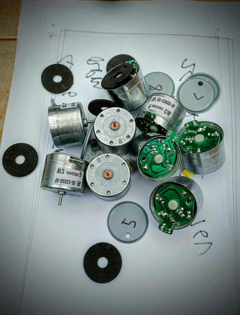
After butchering an old tape deck, and looking up specifications of motors, I found a decent candidate, the EG-530-AD CW. It looked to have a suitable torque, power consumption and RPM/Volt range. The best thing is that they’re available on AliExpress for 50p.
By Grabthars Hammer, what a savings!
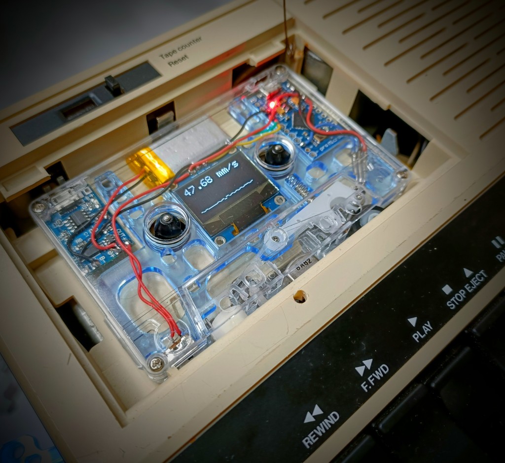
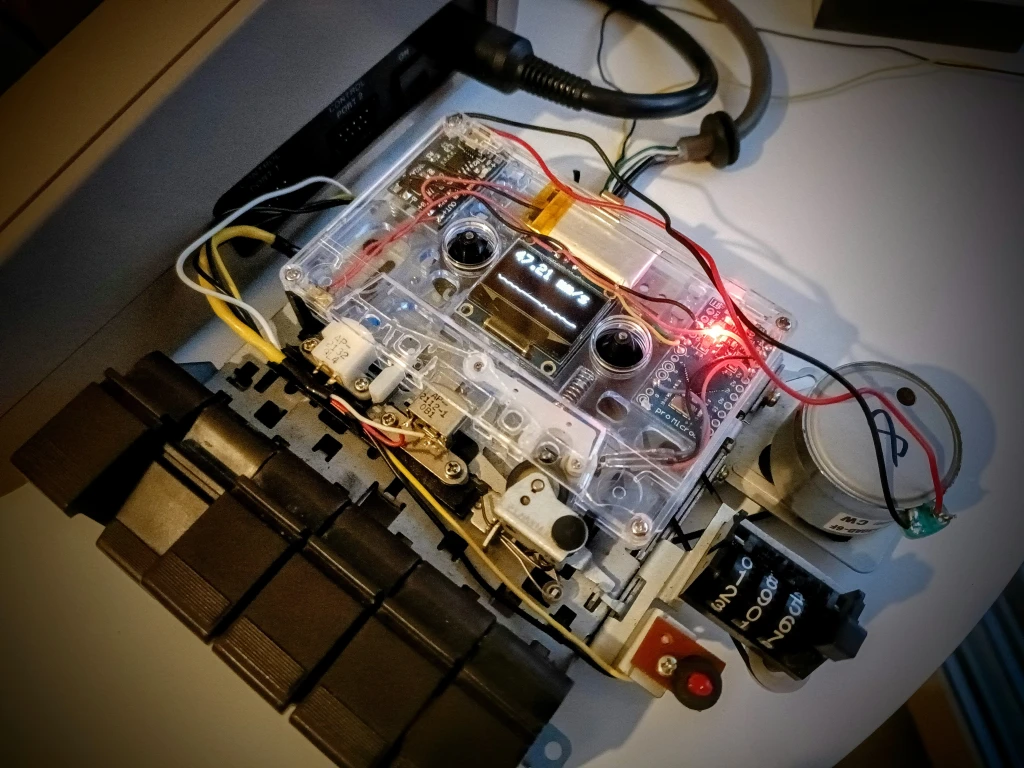
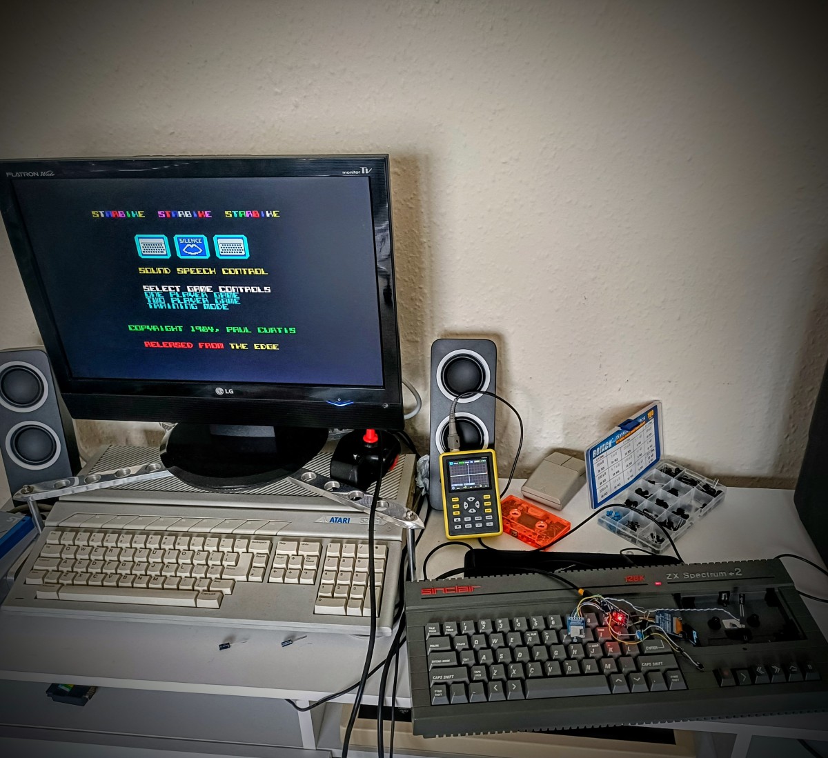
Whilst waiting for them to arrive, I armed up with some tools. I already made a Diagnostic Cassette that has a sensor at the pinch roller calculating CM/S speed. After a bunch of tweaking, it’s so sensitive, it works as a rudimentary seismometer (Oh, I had a proper chuckle when I noticed that!).
It’s great for checking speed and consistency, I’m going to need that if I’m going to get the ideal 47.5mm/s.
It even has a wibbly line!
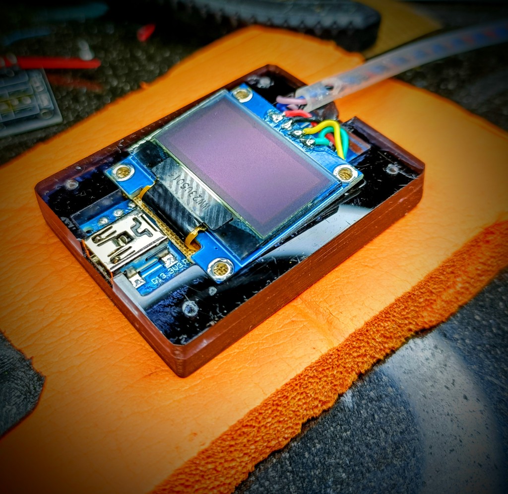
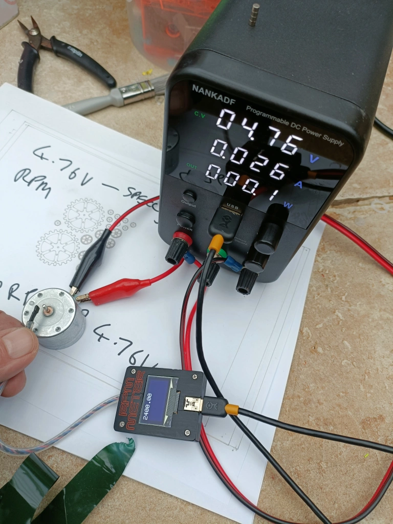
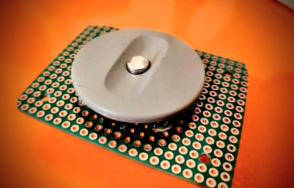
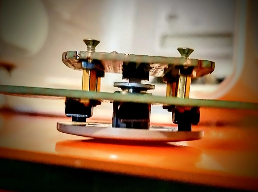
To save me having to keep swapping out motors, I made a small RPM meter so that I can set them separately. The plan is to set one, record the voltage and RPM, then set the rest to that.
It works with a hall effect sensor at the end of the tube, I’ll pop a magnet on the shaft (of the motor) then tweak them up.
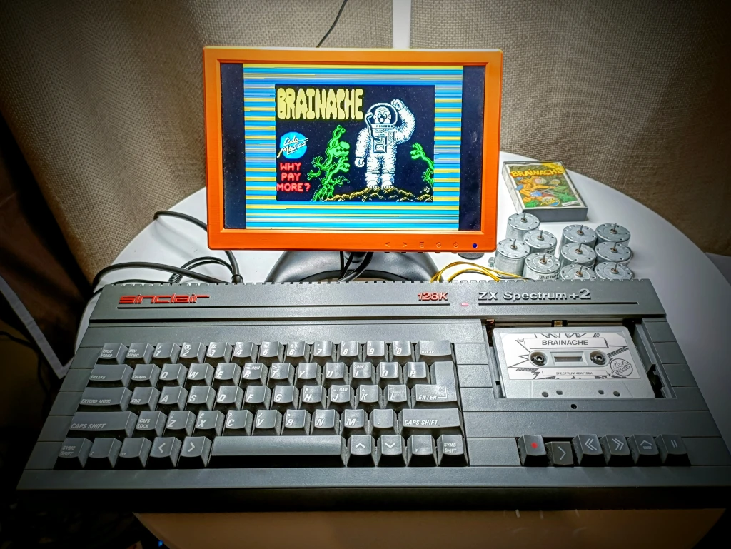
They finally arrived and I speculatively popped one into the Stunt Speccy. It was too slow from the factory but it was consistent, and worked!
Yay!
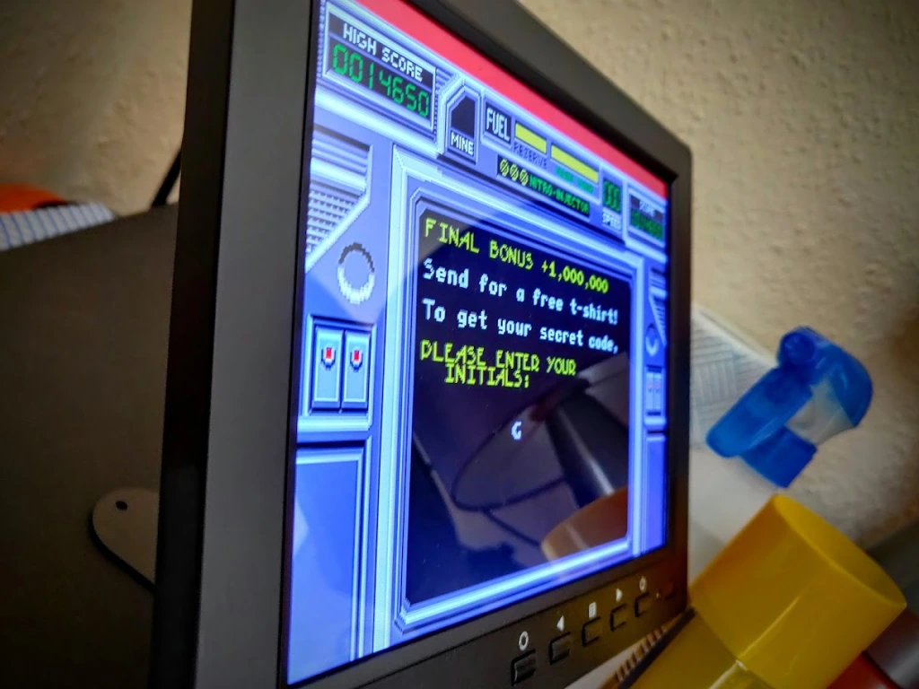
Out of the box, they run at around 2300-2340 RPM. I pulled the numbers from the +2 after adjustment and it needs to be around 2400RPM @ 4.76v.
After that, I calibrated the rest of them and took resistance readings to get an average when I was done. The idea behind this is that you can measure the resistance of the pot to get a rough idea of where to turn it for the right speed.
The average in this case was 165 Ohms. That’ll get you roughly where you need for the +2.
For giggles, I put one in a C64 Datasette, it came out much too slow but a quarter turn from center of the pot brought the speed up.
I’m quite happy with these and will get around to replacing all the motors in my machines. They have an identical bolt patter but as an added advantage, they have a smaller diameter. This means they don’t resonate against the case. That, and the fact they they’re new makes for an eerily quiet drive. 🙂
They’re probably not genuine Mabuchi motors but for retro machines, they’re ideal.
I have the tools but as a rough guide, for the +2, set the pot to about 165 ohms, or about an 8th of a turn to the right from the default.
You can always listen to a tape and compare the tone to that of an emulator, tweaking the pot as you go to match the pitch.
For the C64, that’s a tricky one but as a rough start, tweak the pot a quarter turn to the right from the default, that should get you close enough to load.
Another way (barring RPM meters and all that junk) would be to record a program to the cassette, then listen to that cassette in another audio player compared to the lead in an emulator, it’s a faff but that’s the best advice I can offer.
As far as I know, this swap out might be common knowledge but I’ve been interested in replacement deck motors for years and haven’t seen a decent resource until now. This is as close to a like for like replacement as you’ll need and my hope is that it breathes some new life into some old kit.
As with all my other blog posts, the advice, techniques and methods come with my iron clad ‘Better Than Nothing’ guarantee.
Seriously though, good luck and I hope this helps. 🙂
I won’t waste much of your time so this is a no nonsense, picture full guide.
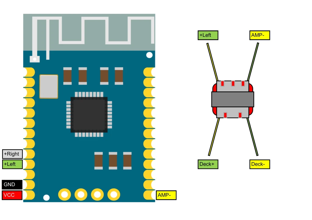
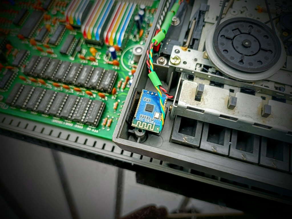
What: This is a mod for a Spectrum +2 Issue 3 to add internal Bluetooth using a BT401 Bluetooth Module and an Audio Isolation Transformer tapped into the Datacorder to load games from a phone or Bluetooth enabled device. It’s quick , easy and costs about £5 in parts.
This is the basic wiring diagram showing the transformer /BT401 connections
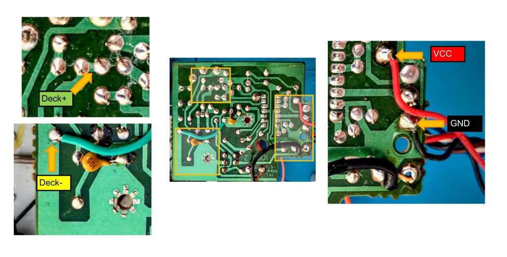
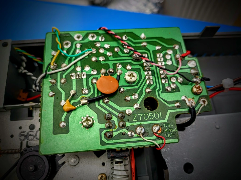
This is where they go in the Datacorder:
The reason for the Transformer is because the Speccy has a common audio ground but the BT401 has an AC signal that is centered on 0v. This makes the amplifier very unhappy so to counter it, the BT401 AMP is isolated from common ground by a coil in the transformer which is then fed to the outpur on the Datacorder.
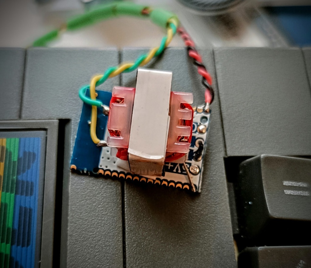
For my installation (Which I still need to tidy up) I soldered the transformer directly to the BT 401 and secured it to the transformer with some double sided tape:
Which I then tucked neatly on the inside of the Datacorder shell.
How to use?
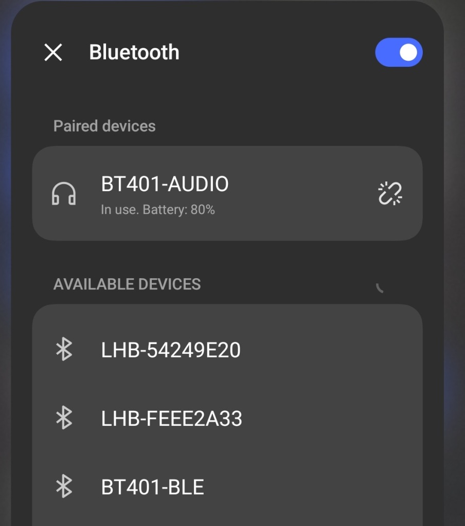
When you power up the Speccy, if everything goes well, the BT401 Module will output a status tone and will be ready for pairing. You should check Bluetooth on your device and look for BT401-AUDIO, once paired the Speccy will output a tone and you’ll be paired.
Select the BT401-AUDIO device on your phone/tablet as the audio output and then use PlayTZX to load games onto the Speccy. You may need to experiment with volume levels but I’ve found StrangeLoop loads when the phone is at 100%. I recommend starting at full, testing Strangeloop, then dropping the volume if you need to and trying again until it works.
I’ve been using this mod for a day or so and it works really well. It’s cheap, easy and adds a great feature so I had to document and share.
Hi, I’ve been faffing with the TZXCassette and I never could get Head over Heels to run properly. I would like to make the Cassette as device agnostic as possible and this means that the filtering had to go.
To save space, instead of a full sized Cassette head to send the signal to the Speccy tape head I used a 10mh inductor, a coil is a coil right? This was both an excellent and terrible decision.
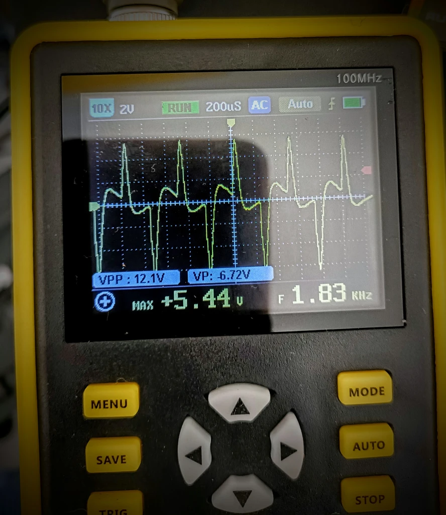
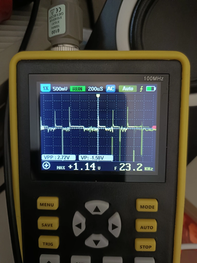
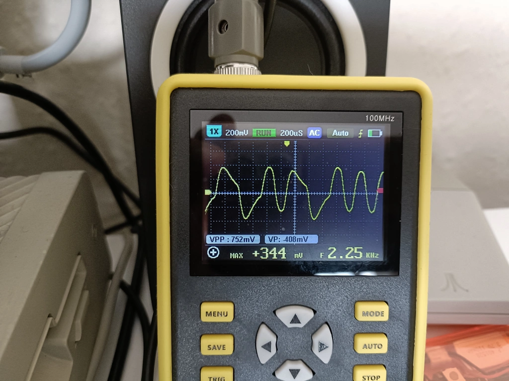
Using the inductor had plenty of volume but that distortion I had in the previous post was back, and with a vengeance! This is what the tape deck is seeing:
Oh wonky waveform, you appear with the tedious inevitability of an unloved season.
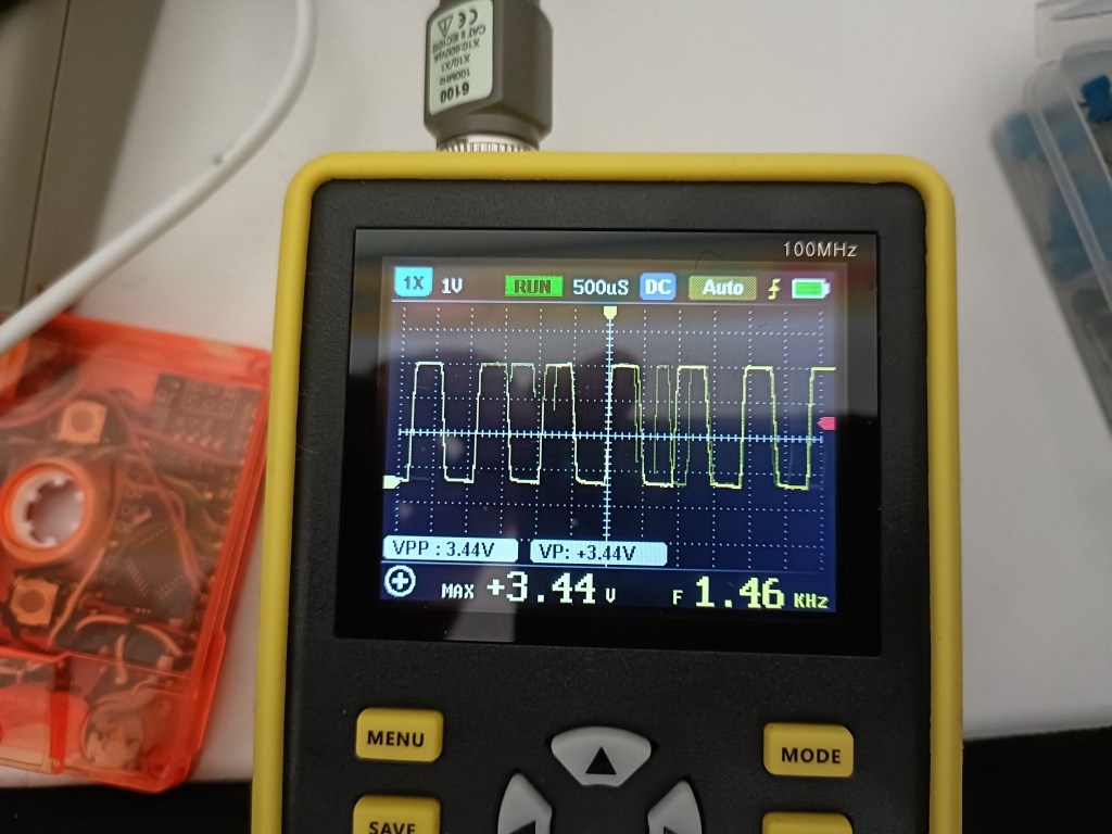
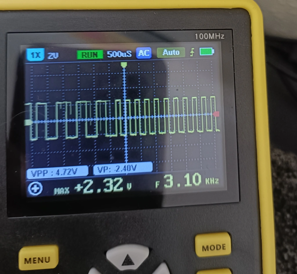
And this is monitoring the signal to the tape head.
What the flip are those spikes?? I didn’t understand what was going on at all. Without the inductor, the waveform is absolutely lovely, as ideal as it gets.
Hmmm…
I’m often in a situation where I need to work out something that I have no clue about and I have a process of sorts. it involves poking at a problem until something diagnostically interesting happens, then going away and having a think about what I’ve done.
All I had by way of a problem statement was “Inductors make a big spike, it is not helping”.
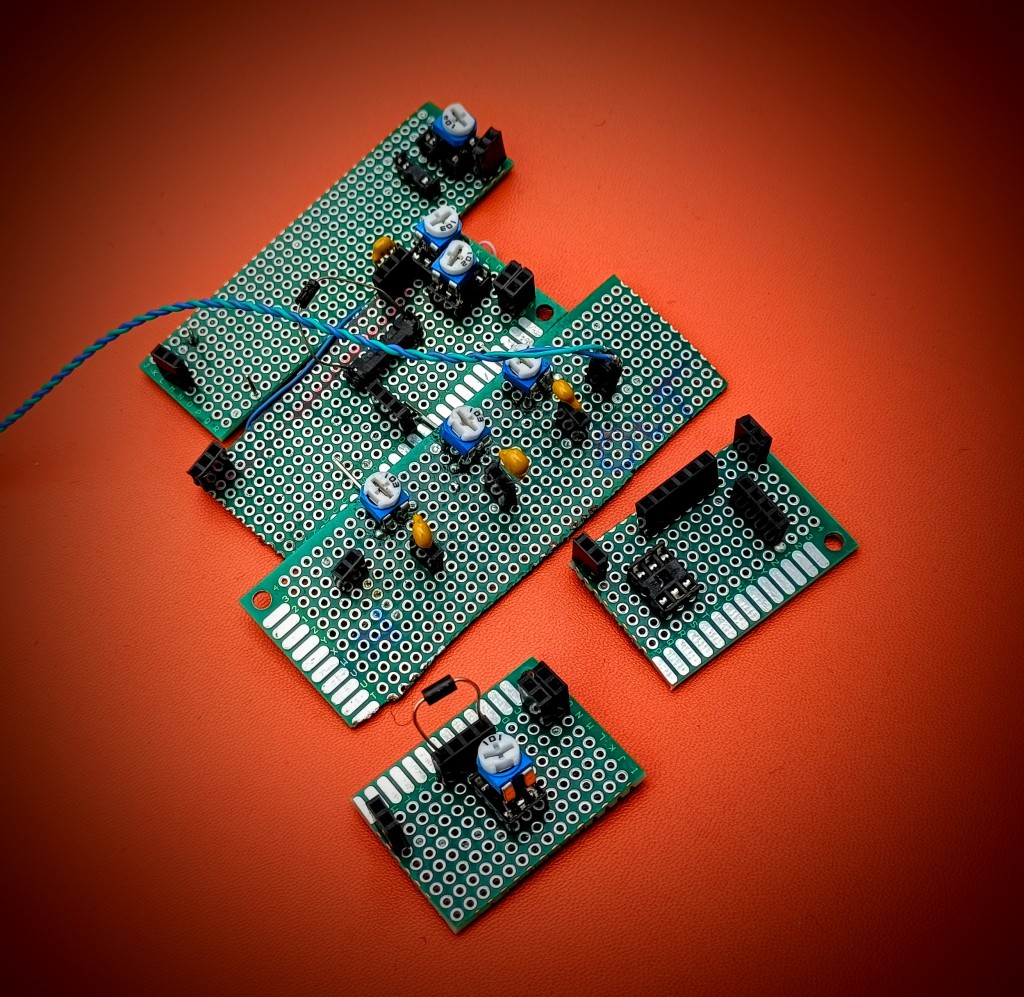
I did a bunch of Googling (then switched to Ducking ‘cos Google is terrible!) then I made myself an impressive array of high pass, low pass, band pass filters and poked at it for about a week without much of a change.
I noticed something weird. When I had filters applied, I got some improvement but nothing was working as I would expect. I tried putting a variable resistor in line and adjusting it but I was getting a low pass filtering effect which shouldn’t happen.
I decided to read up on inductance in more depth and that’s when I realised what was happening. Short version: An inductor’s gonna induct.
Long version (buckle up!)
The voltage is being applied to the inductor, the inductor then generates a magnetic field. The problem happens when you switch the current off, the field in the coil collapses and the flux has to go somewhere. It gets converted back to electricity, and dumped back into the system, creating a massive voltage spike.
(which is why the resistor worked like a low pass filter, because it was!)
It turns out that if you’re stupid enough to put 5 volts into an inductor and rapidly switch the power on and off, the inductor will charge like a capacitor. Depending on the pattern of short and long spikes, it would charge to a greater or lesser degree.
I now knew I was looking at an inductance spike and apparently, the way to fix it is to put a flyback diode in. I knew nothing about diodes other than they’re ‘one way valves’ and after a bit of research, settled on a 1N5817 Schottky diode and put it in parallel.
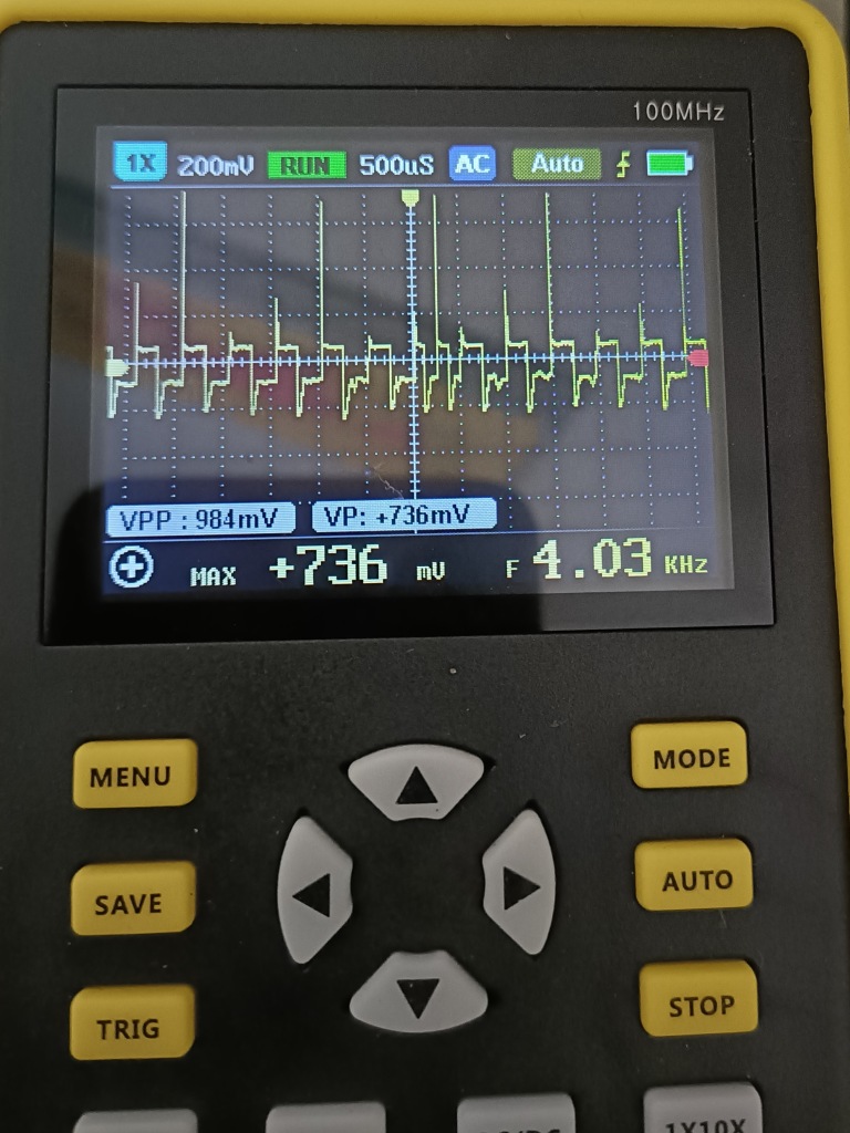
It was immediately better! Still some spikes but nothing too terrible. I filtered it, and got to a smooth waveform.
I set about testing games and got to a sticking point. I could load everything except for Gilligan’s Gold (with a 33uf cap across the inductor) or load Gilligan’s Gold or nothing else (with a 220uf cap). Something still wasn’t right.
A Speccy will determine a long or short pulse by checking the distance betwen the crossover points (I think) and filtering subtly changes this to the point where some speedloaders will not work. Those remaining spikes needed to be squished, but how?
The current was being blocked from being reverse dumped back into the circuit by the diode but it had nowhere to go and was still making those spikes. Just for laughs, I put an original cassette head on and tried it.
It was perfect! Still a little shimmy on the tops of the waveforms but those verticals are super crisp. This is because the tape head has a resistance of 220Ohms and is dissipating the energy that would normally bounce around ruining my day. 🙂
Absolutely everything loads now with freakish reliability and all it took was a 2p diode!
This means I can continue my TZXCassette v3, the idea is to get it working on as many systems as possible and an unfettered signal will help massively. It would be like whack a mole otherwise, a tweak for one system would knacker another.
A special thanks to my Stunt Speccy. It was cobbled together from bits and has taken a real hammering for years. it is currently lidless on my test bench.
When I’m done with this project I might get it something nice. 🙂
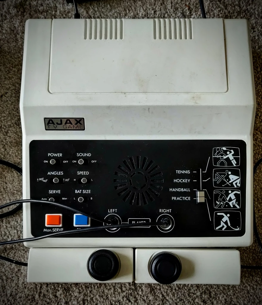
Hello! I hope you’re well! I’ve recently finished restoring all my retro stuff and I’ve picked up a few tips on the way that could help your kit look extra nice.
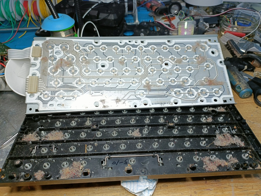
Brief preamble. Usually, getting a retro machine comes with decades of dirt, grease, grime and ick. They also smell of ‘other people’s houses’ so the first thing is to disassemble and give it a good clean.
Cleaning, and ‘types’ of dirt:
I have my own philosophy on filth (filthlosophy if you will.) it isn’t backed by any science I’m aware of but it works, and rather well too.
Clean Dirt – Dust, fluff, dry stuff. Anything biologically harmful, if kept dry would have died off long ago.
Dust, fluff Dry stuff!
Best loosened with a 2 inch paint brush and blown off with HPA (High Pressure Air). This also works for morherboards but when doing those, I put some tin foil across the back in case the air and dust colliding builds up static potential. I probably don’t need to but it can’t hurt right?
When doing this, do it outside. No, it won’t launch you straight into sepsis if you breathe any in but it’s still pretty nasty and the local birds can get some vintage nesting material.
If you get hairs stuck in odd places (on the thing you’re cleaning!) fabric softener works and helps to loosen up fibres. Incidentally, it also helps when getting hairs from brushes.
Dirty Dirt – Blood, sweat, gravy, and egg. Anything harmful, mold bacteria etc.
I don’t have any pictures of anything moldy (who would!) so here’s a picture of a local Cat, he is called Mark, he is an asshole.
Nuke that stuff from orbit with a big tub of bleach. I’ll make a reasonably strong solution and dunk it in a tub for a good half an hour then I’ll put the gloves on and start scrubbing. I’ll do this to all my kit anyway. I use a soft kitchen scrubbing brush, try to use something stiff enough to do the job but fine enough to get into the nooks and crannies. A 2 inch paint brush with the bristles cut down to about 40 mm is perfect for this too.
**Note – be careful with bleach and IPA on stickers, decals and paints etc, if you’re not sure, use Elbow Grease instead.
Greasy Dirt – Teen Grease, oils, and other oddly waterproof residues.
If a good soaking in water isn’t enough, then a spray down with Elbow Grease and a wipe should cut through most of it, for anything else, IPA and a wipe should help, being mindful of any decals. I’ll go over the shell first with a brush and IPA, then blow anything else off with a compressor. It will remove all the surface grease, and may remove a depth of colour from the shell and make is appear slightly patchy. Look up Microcrystalline Wax, later on, that stuff is AMAZING!
Sticky, and water soluble dirt – Spilt sugary drinks, smooshed in sweets, general grubbiness, etc.
Let water and time do the work.
Soak in warm water for long periods of time, and agitate regularly with a dishcloth, this stuff is easy to deal with. If there are any tricky corners, a cut down paint brush will be your best friend.
I have been known to clean these while showering, it saves water and I use Head and Shoulders so it won’t have dandruff.
Adhesives – Stickers, that Weird Brown Glue stuff, marker pens.
Weird Brown Glue Stuff – What even is that stuff anyway?? Stubborn, that’s what!
Security marker is particularly challenging but patience, and repeated dousings is key.
For most stickers, soak in water and washing up liquid for half an hour, and occasionally rub at it until the paper layer comes off. After that, WD-40 should get the sticky off and a quick wipe with IPA will finish it off.
For marker pens and Weird Brown Glue, IPA will work. Sometimes, for stubborn pen marks, you can use bleach to kill off the pigment. For Weird Brown Glue – This takes time. Soak in IPA, wipe off the top layer, then keep going until you hit plastic. Keep using fresh disposable cloths or it’ll just stick back on again.
For security marker and/or stubborn pen marks,soak a paper towel in IPA and leave it on top of the marks, then swab, and replace the towel as needed until it goes, a little agitation with a cut down paint brush helps too. You’ll see if it is still working as you’ll have a residue on the tissue.
Improving the finish.
Once your machine is clean, you can start working on the finish. I’ll try and group them into types:
Piano Black/perspex lenses.
Yep, that’s a gouge!
Shiny surfaces pick up scratches over time, given enough time, it can end up looking like the front window of a long abandoned starfreighter.
**Another note, be careful with abrasives, they’ll take any decals or logos straight off. If you absolutely must use them, use them sparingly and only when you have to.
First sweep – Make sure the surface is clean and dry, and then go over it with Plastic polish using gentle but lots of sweeps. I use either Regina Blitz, or cheap tissues, some cloths and kitchen roles are slightly abrasive and you may end up putting more scratches in than you take off.
Second Sweep – Inspect the surface for deeper scratches/gouges. You can get some success by resurfacing with 1000 grit wet and dry sandpaper, be mindful of how much material you’re taking off.
Try to sand a large area around the scratch, if you concentrate on a small area you could create a divot that’ll look weird. Try to bring the surface down to the bottom level of the scratch. If you’re super fussy you can use 3000 grit to finish, it’ll save on hand polishing later on.
Final Pass – Using tissues (Or Regina Blitz) polish up, and down, and then left to right making sure you use lots of light passes. it helps to keep the item flat on a desk.
Huzzah!
Matt/Textured Shells (or, the first rule of Microcrystalline Wax Club is to tell EVERYONE about Microcrystalline Wax Club)
I used what I call ‘Miracle wipes’ and they really help get a lovely even finish and deepen the shade of the shell. Get a small cloth, and add a gob of Renaissance wax, then spray some WD-40 on it. go over the shell in small circular motions. leave about half an hour for it to dry then buff gently with a soft cloth.
My thinking is that WD-40 thins down the wax, and allows it to seep into the microfissures of the plastic. It also seems to cover some of the damage done by RetroBrighting, here’s a grey +2 shell with mottling:
After a go over with Miracle wipes and a buffing, it has a nice, even sheen, isn’t slippery like silicone products and it also smells great!
PCB Cleaning
Not too tough, I’ll douse the whole board in Isopropyl Alcohol, and give it time to soak in. I’ll rest the PCB on some tin foil in case of static.
Agitate with a cut down paint brush – The bristles are granular enough to get into the tiny areas and do a good job without being so stiff it bends the components. After that, give it a few good blasts with high pressure air. Again, do this outside, unless you like feeling dizzy and sick and thrive in a potentially explosive atmosphere. Once done, you’ll have lovely, flux and generally ick free board!
Weapons of War!
These are my go to tools and products, I’ll list out their best usages below.
Renaissance Wax: This is a microcrystalline wax that’s a game changer. It is used for antique restoration asnd museum preservation. It protects from fingermarks, restores and deepens the finish, it leaves a sheen rather than a shine on textured shells. You can apply it with a cut down paint brush to work it into textured areas. It can even reduce the scorching done by poor retrobrighting. It can be used on plastic and metal, wonderful stuff.
Shines where it needs to be shiny and sheeny when it doesn’t. 🙂
Mother’s Mag & Aluminium polish:
If you want something to be shiny, this is the stuff for you. It starts with microgranules that get smaller as the paste is worked in this means that the ‘grit’ gets smaller and smaller as you use it.
On Aluminium and plastic, I can go from a sturdy 1000 grit straight to this stuff and it takes it the rest of the way. I’ve stopped using plastic polish on Perspex as this stuff is way better. It also leaves a preservative wax coating behind.
This is best used in the end stages of the polish with fine tissue paper , as mentioned before some cheaper kitchen towels are quite abrasive.
So very shiny!
Cut down Paint brush
Great for getting into stubborn areas, you can get a set and vary the length (aka cut with scissors) to get the right level of stiffness. About an inch and a half is perfect for PCBs, half an inch for scrubbing textured cases.
Isopropyl Alcohol (IPA)
My go to cleaner for everything, bathrooms, glasses, and PCBs, great for getting labels off and preparing surfaces for any kind of adhesion (Quick tip, when adhesive manufacturers say keep the area clean, and grease free, they’re not kidding!) .
Elbow Grease: A great general degreaser and cleaner. Use this as a second sweep after bleaching. As a bonus, the spray tops screw straight onto a bottle of Isopropyl Alcohol for bulk sprayying action.
Magic sponge Good for matte cases, and for removing really stubborn marks, it is abrasive so use sparingly.
The Pink Stuff The nuclear option, only use for spot cleaning. It is really coarse and best worked in with a paint brush cut to about half an inch. Work it into textured shells with small circular motions. ONLY FOR EMERGENCIES!
Regina Blitz Kitchen Towel. Tough enough to get most jobs donebut also doesn’t abrade the surface likel other towels can.
Bleach It’s bleach, you know bleach yeah? 🙂
Cleaning checklist:
Disassemble
Soak shell and any other parts in warm bleach solution for about an hour. Scrub. Apply Elbow Grease. Scrub. Remove any final marks. Rinse and leave to dry.
PCB
Place on tin foil, and spray with IPA. Agitate with cut down paint brush. Blast it clean with high pressure air. Repeat until spotless.
Polish any lenses or glossy plastic with Plastic Polish and or Mother’s Mag. Inspect for deep scratches. Sand area down with 1000 grit wet and dry. Polish again. Repeat until done.
Shell restoration.
Put some microcrystalline wax on a small cloth, spray with WD-40 and mix it together. Apply to the shell in small circular motions, work into deep textured plastic with a cut down brush. Wait half an hour for it to dry. Buff off with a soft cloth. Repeat if required.
After this, you should be ready to assemble your shiny new retro device – It’ll look nice and not smell of other people’s houses!
Before and after pics: I’ve used this method many times, here are some before and after pics:
And finally, my latest one – A grubby ZX Spectrum 128k +2 (Issue 3) Went from this:
My previous FatScreen Mod used an LCD and the viewing angle isn’t great. It was okay up to a point and then, at extreme angles the illusion would be sick down its top. Now my project budget has been expanded, I’m going to commit to doing it properly.
Lockdown taught me not to rush a project and the only deadlines I have are set by me. Corner cutting might save an hour or two here and there but with this project, mistakes will cost days and bodges would bother me forever. I’m going to go at this like a Discworld Golem, steady, constant, and more important, carefully!
I’m using an 8 inch IPS 4:3 display, it’s the ideal size, the colours are really vivid and the viewing angle is amazing!
Lovely!
It’s all well and good having a shiny display but it needs to look a little less modern, it’s a retro monitor after all. I need to find something to put it in.
Normally, I’m completely against drilling and generally hacking up retro stuff but in my defence, I’ve lost count of the machines I have repaired and refurbed. I’ve invented a few non destructive mods and, if I get it right, this will be a proof of concept to see if machines with built in CRTs that have died can at least retain their old aesthetic with newer components.
I’m going to allow myself this one, and as penance for chopping up a shell I’ll make sure I do my level best to do it justice.
I kept an eye on eBay for something suitable but couldn’t find an 8″ CRT anywhere so settled on a 5.5 inch that could be chopped about to fit. I waited a week, still not posted. It wasn’t going to arrive any time soon. Hmmm. Back to eBay…
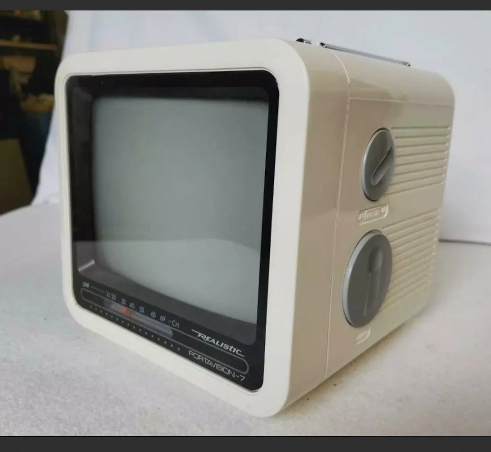
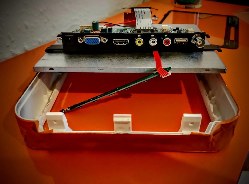
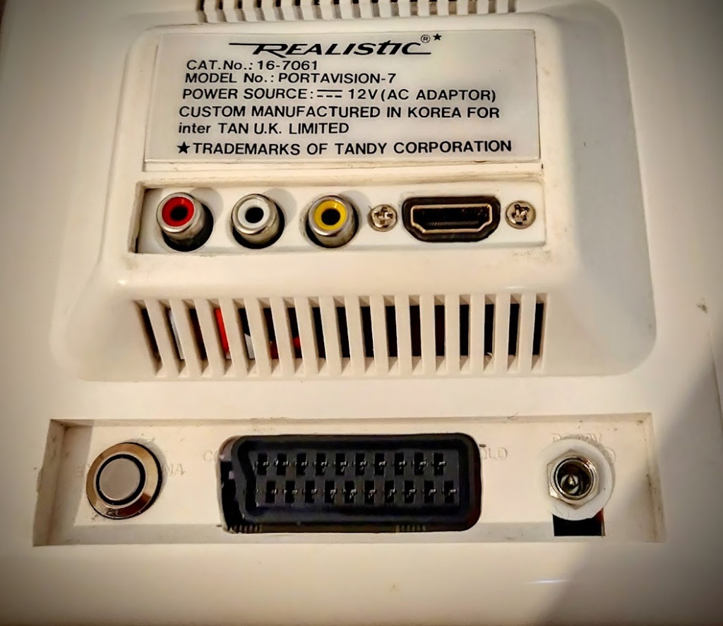
And then I saw it! A Realistic Portavision-7, it had exactly the look I was after, it was a 7 inch and I had an 8″ display but I did some rough mental arithmetic and I should be able to fit it in thanks to the frame.
I still had the other CRT in play on eBay but thought I’d try my hand.
I showed my other half and she agreed it was perfect but in retrospect I should have just placed a bid on it quietly. I always wait until the very last moment on eBay, I don’t want to tip my hand and bump up the price in a bidding war.
With three minutes to go, my partner started getting really tense and kept asking me to bid. To keep her (and me!) calm, I laid out a nice tale.
I said “It’s like those scenes in films where a bunch of archers are defending a castle, the enemy is advancing but you need to wait until the last second as you only have so many arrows.”. She countered with “But if you don’t fire in time you’ll die” – Good point well made! 🙂
Two minutes to go, we’re watching the item like hawks while I say in my best Kingly voice:
“Hold.”
One minute to go:
“Hooold.”
Thirty seconds:
(My partner is curled up like a prawn on the sofa wringing her hands telling me to bid…)
“Hooooooooooold!
Twenty Seconds:
“Ready!!”
7 seconds:
“FIRE!!!!”
Cue a blank screen for about 15 seconds while we looked at each other, then the screen, then each other. I won! Huzzah!
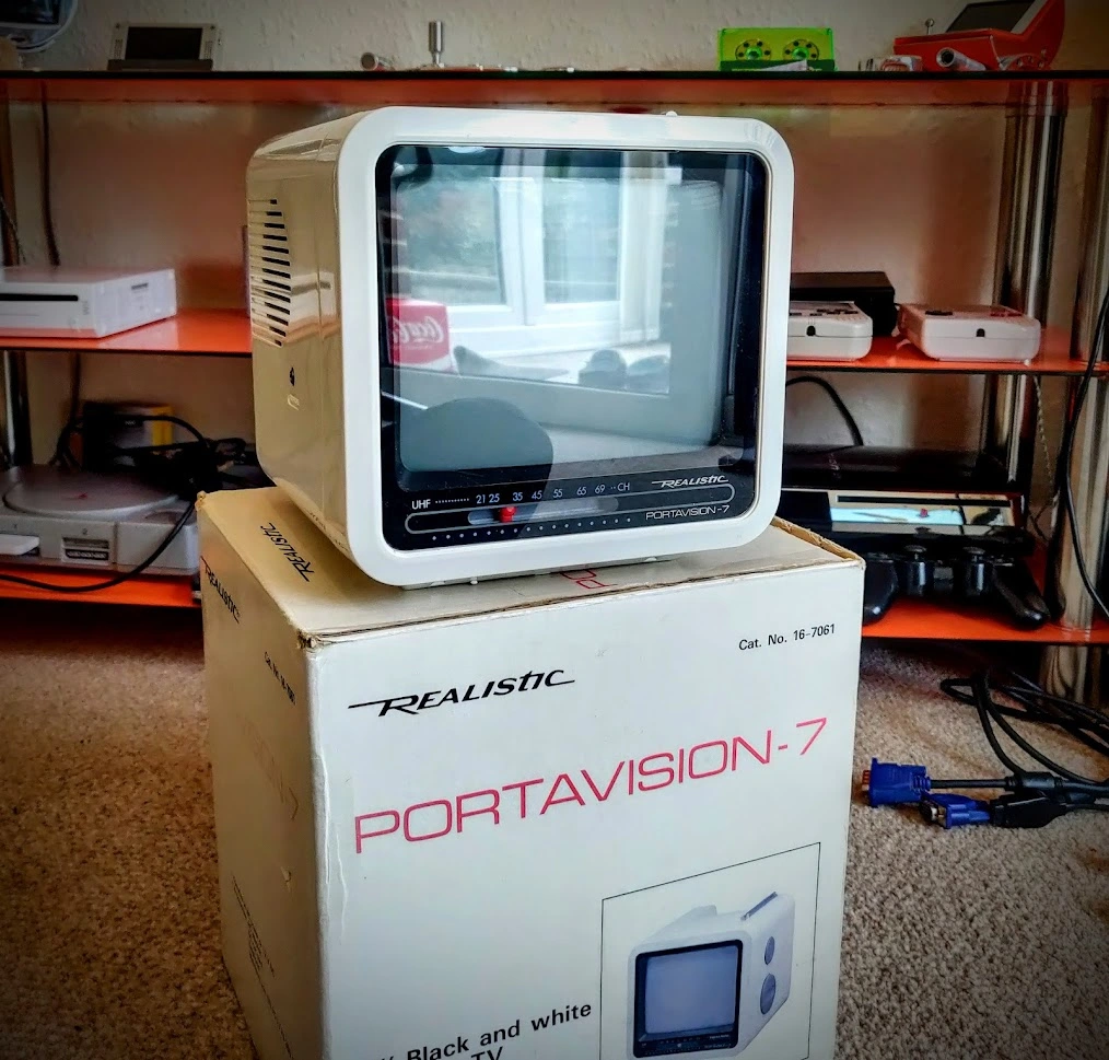
The seller posted really quickly and it arrived in a few days, beautifully packed!
Nummy Nummy Num!
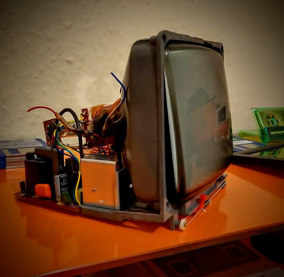
I needed to disassemble it, but CRTs give me the willies. A cut finger I can handle but one mistake with those and you’re dead without even knowing you messed up. *shivers*
I asked Twitter for advice, normally a bad idea in a general sense but the corner of Twitter I inhabit is a lovely little retro echo chamber where everyone is lovely.
(Especially@SmileyBobUK, an all round great guy who always knows the right thing to say when a project is going south. I couldn’t have done the first one without his support and encouragement If you’re reading this Bob, Thank you!)
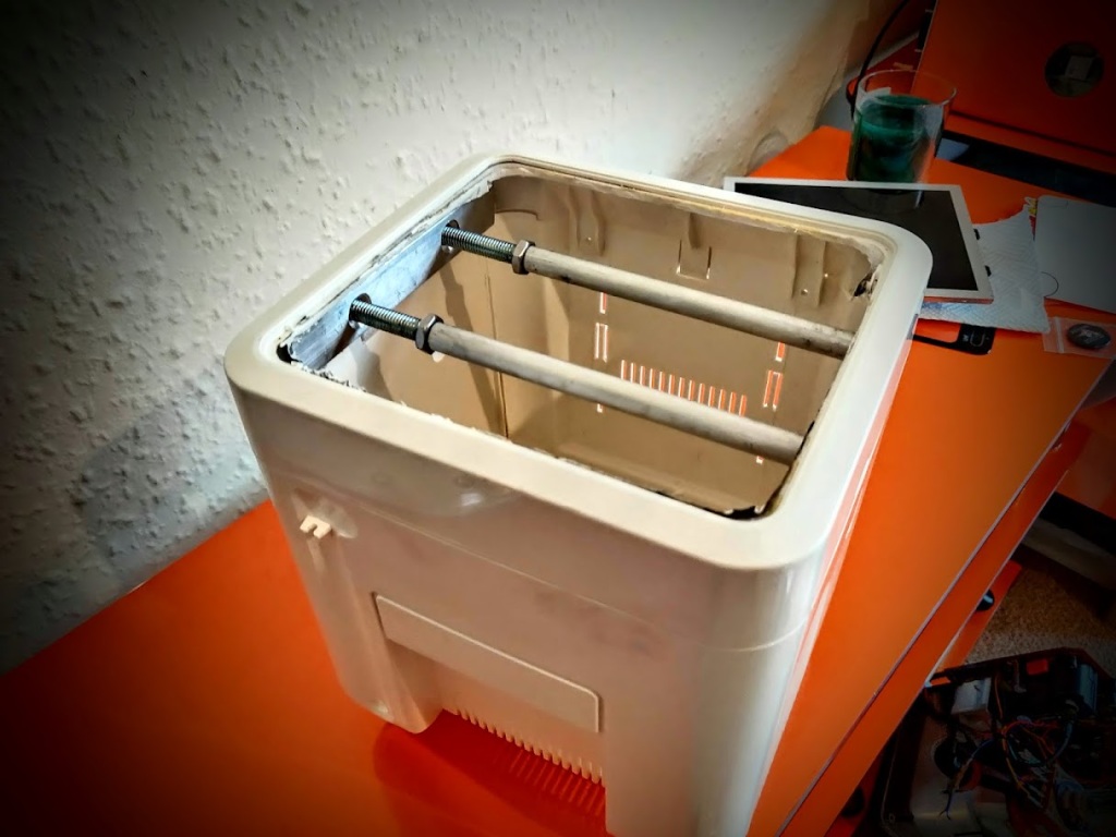
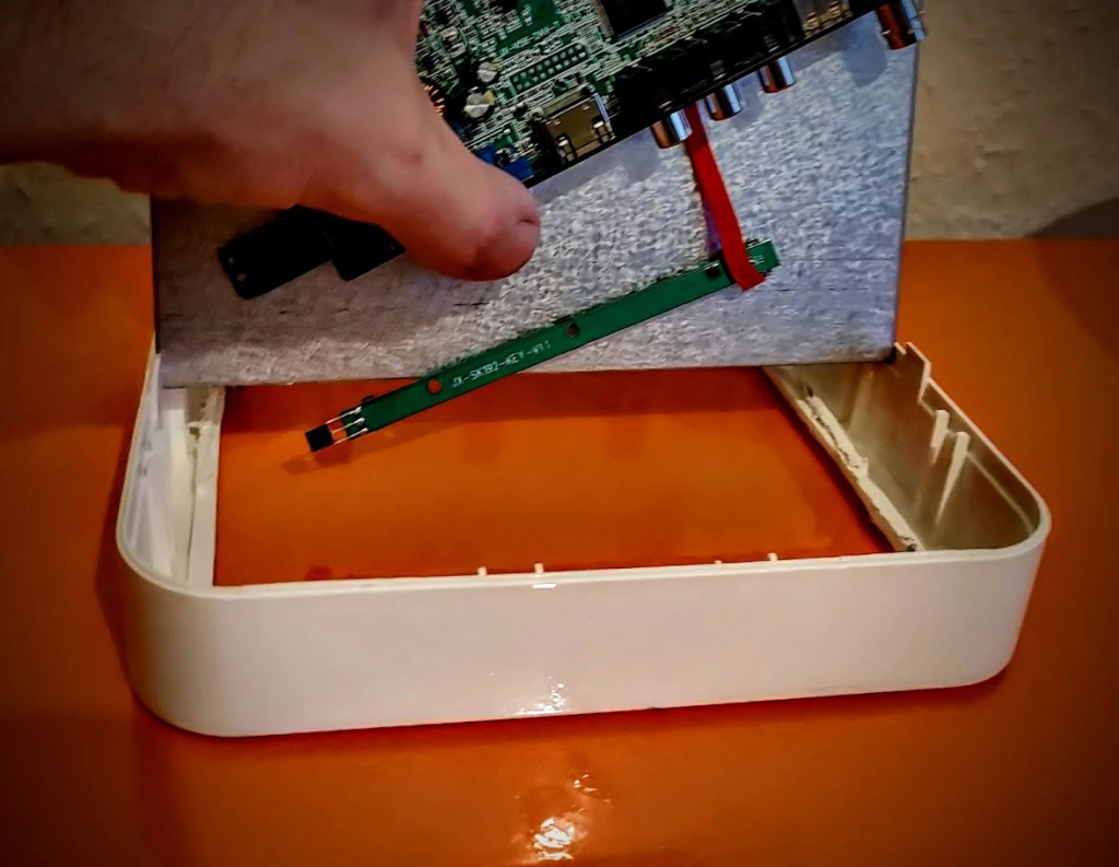
I got all the right advice, and gauntleted up, using the one hand rule, I extracted the tube and didn’t die – Yay!
I’ve kept this undamaged and it apparently worked fine so I’ve kept it aside in case anyone wants it, waste not, want not.
Now to see if the display fits in the shell…
Shit.
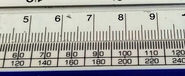
Note even close – WTF! It turns out that I was using a ruler I got for free and it has some sort of weird witchcraft measurement system, just under centimetres, I was sure I had enough wiggle room but apparently not.
The top is in centimetres, as for the bottom, I have zero clue!
I noticed the shell was warped too and it curves in, that definitely won’t help. Luckily, using braces and REALLY hot water, you can straighten plastic out. it took a few treatments but got it much straighter.
I decided to take a leap of faith and press on with the shell mods, thinking that I can strip the display down enough to fit it in as they usually have a border of some kind. There is only 2-3 mm difference so I’ll deal with that later.
SQUEEEEEEEEEEEEEZE!
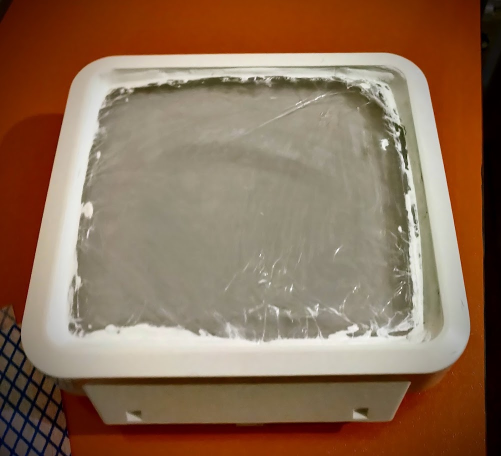
I worked on the bezel first, my plan is to match it to the curve of the lens so used some Milliput to fill in the profile. I wrapped the lens in cling film first as I didn’t want to accidentally epoxy it in. 🙂
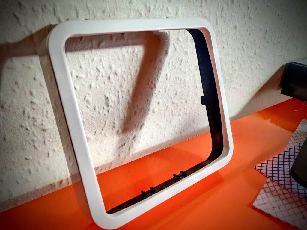
I used all the sanding and filling skills I learned in the 90s on my rusty A.F. MK2 Escort and got it shaped nicely!
Unfortunately, the shell is an off white and there’s a clear difference in the shell and Milliput colour. I gave it a retrobright to bring it up a shade or two.
It still wasn’t enough so I mixed up a batch of ‘wildly inconvenient beige’ from some Revell enamel paints. I made a decent amount in case I needed some later, not a bad match even if I say so myself! 🙂
With the front done, I needed to get to bonding the screen. LOCA adhesive (or at least the cheap stuff I used) tends to weep and contaminate the backlight assembly. I can get on with the rest of the shell while it’s getting its leak on.
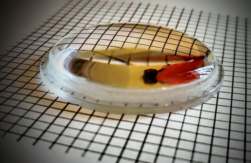
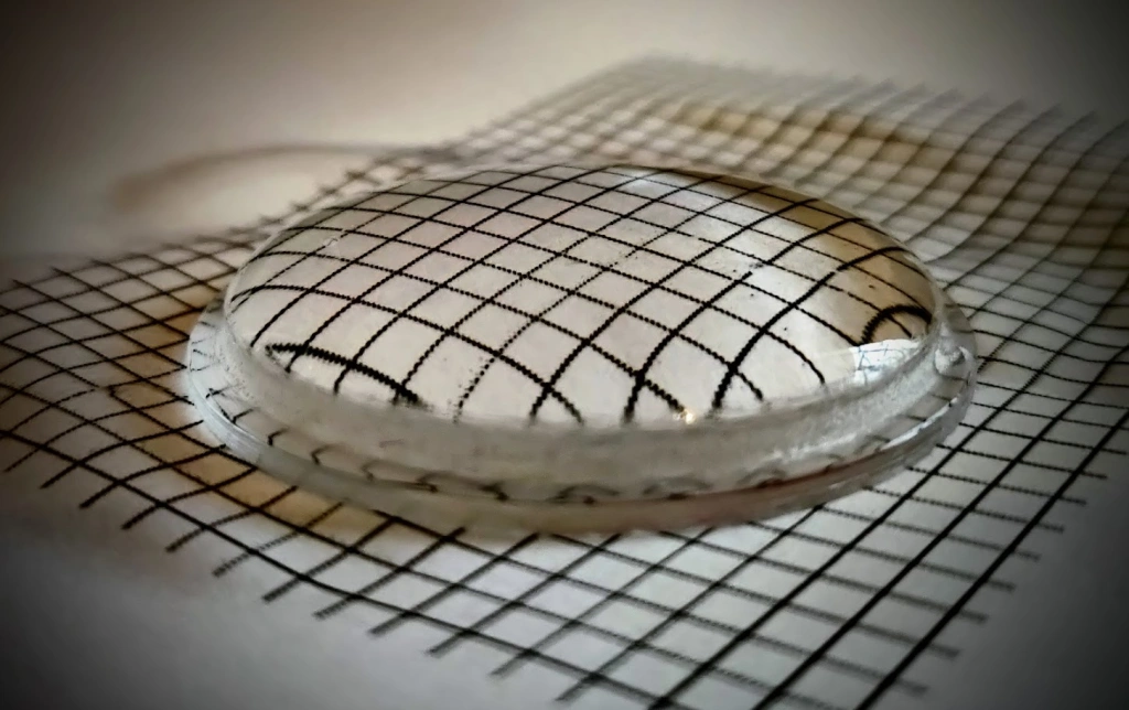
Speaking of FatScreen Technology (Yep, I’m calling it that) I need to explain the reasons for bonding the screen. If you simply plop a fisheye lens on the front of a flat display, you will get exactly that. The light will be scattered between the layers, muting the contrast and the colour.
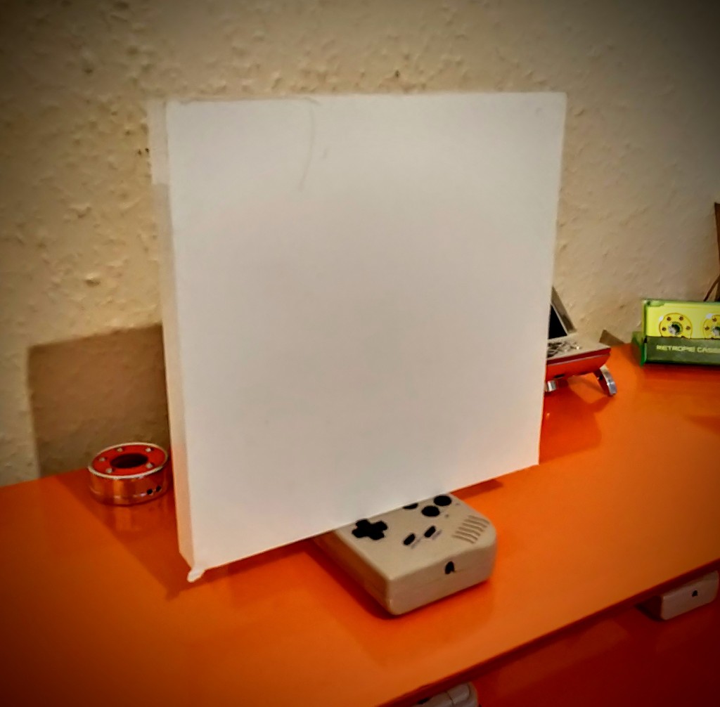
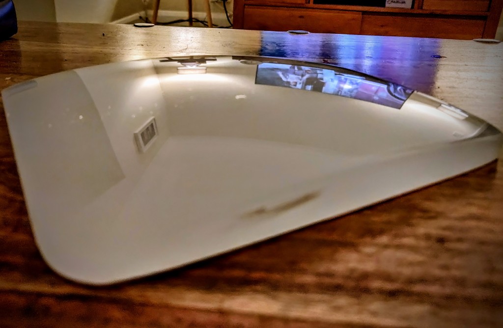
In the image below, I ‘plopped a fisheye lens on top’ it’s a bit rubbish, no bendy.
But in this one, I used a layer of water to optically join the two layers, there is a marked difference, plenty bendy! 🙂
Bonding is not without risks, there’s the whole contamination issue, masking the screen, and cracking, bubbles, lint, snapping the ribbon cable and many many more things to go wrong. I’m pretty sure I’ve discovered every possible way to mess it up, the last one I made took 27 attempts to get right.
I’m going to try to do this right the first time but it’s a massively high stakes project on a much larger scale. if I make any mistakes at all, I’ll have to start again. From scratch.
Normally, I’ll go at a project expecting failure, I enjoy the process of actually making a thing and the end result is a sort of afterthought. It’s a nice consequence free approach and there’s no pressure. This is something else entirely.
I procrastinated for the whole of Saturday – I knew what I had to do but couldn’t quite bring myself to start the bonding process. I pottered about the house, pensively frowning and went to bed slightly stressed about the project.
Me and my OH were chatting over a coffee on Sunday morning and she asked how the project was going. I fessed up that I was scared.
She looked genuinely surprised as I usually go at a project like the Kool Aid Man. In fact, she bought me a t-shirt because she thought it summed up my usual method nicely. I put it on for inspiration.
Defiantly breaking the rules on a flaming pile of trash. It’s just so me! 🙂
Surprisingly, I actually felt better.
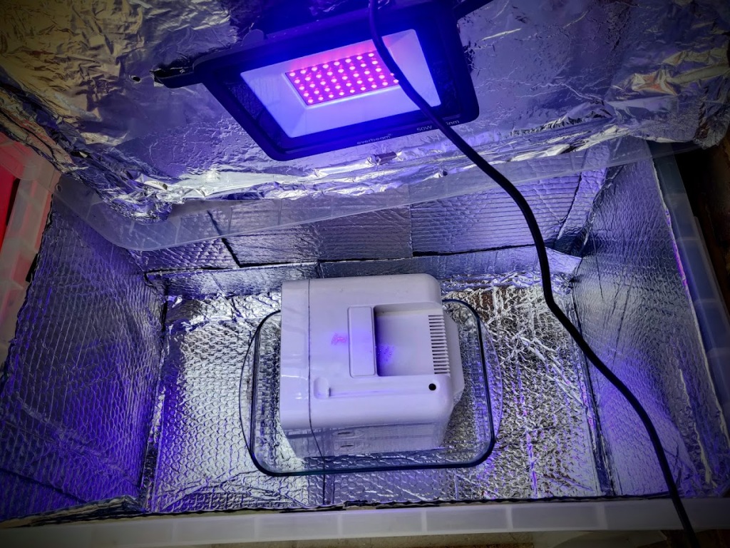
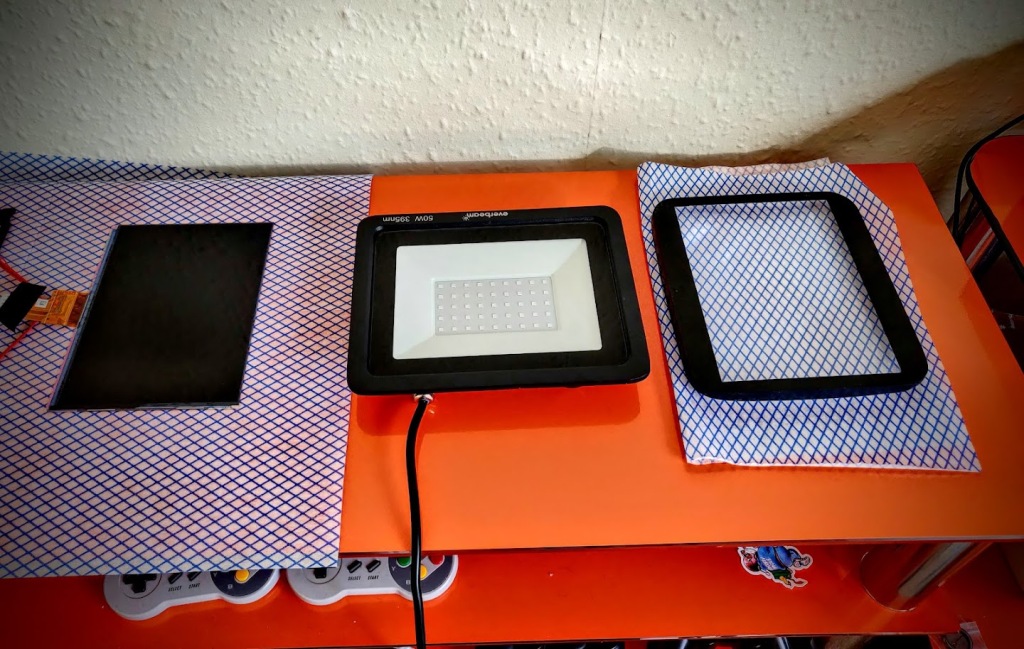
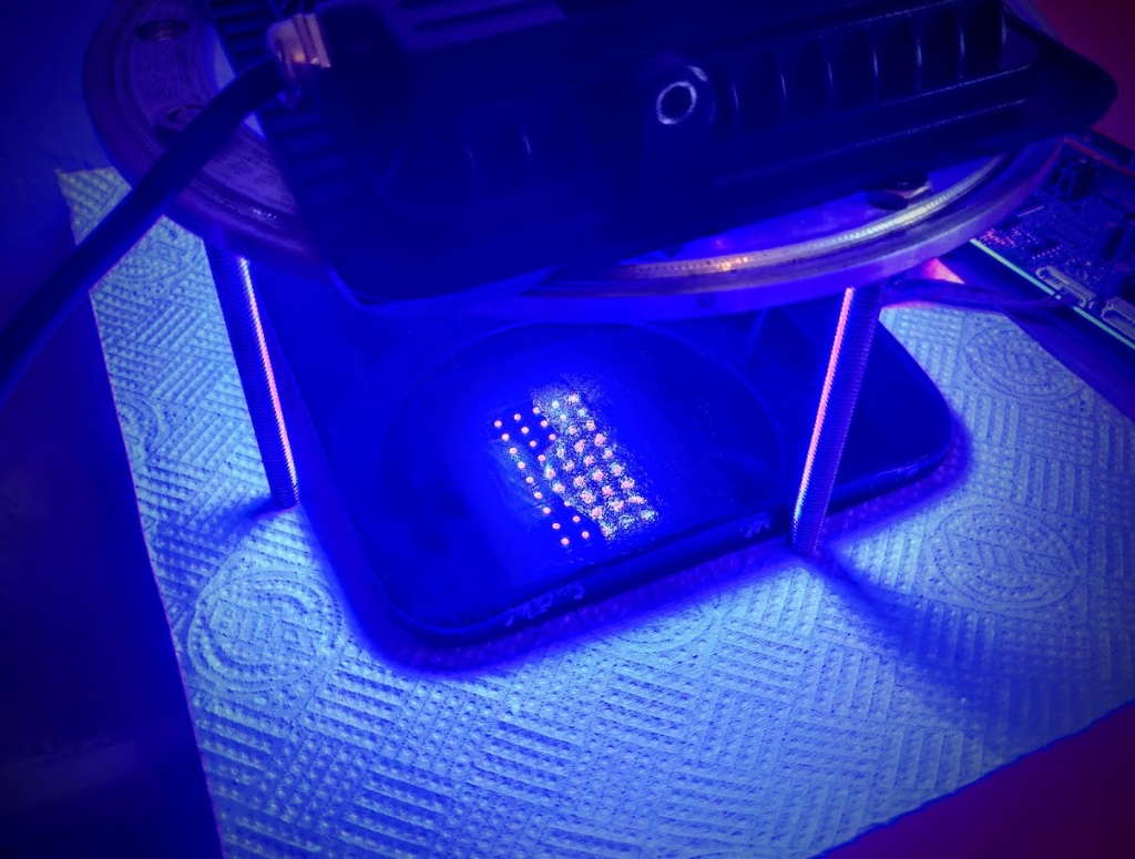
I prepped everything as much as I could, I had reams of lint free paper towels, fine brushes, and even made a frame to put the display in while I nuked it. I was as ready as I was going to be, time to get my Honk on!
I opened the LOCA ready to squirt onto the screen, and then the smell hit me. It has a very distinctive aroma and for me, it’s the stench of failure. Undeterred, I took a deep breath, poured an x pattern on the lens and put the display on top. That’s where things went a bit wobbly.
There were massive bubbles everywhere! The display is really fragile so I couldn’t just push down on it. I rocked it from side to side, and twisted but they wouldn’t move.
Shit.
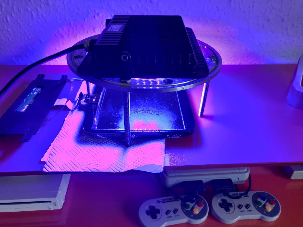
I eventually managed to gently slide the screen off sideways to reset and start again. This time I used a whole bunch of LOCA right in the middle and gently applied the display. LOCA was everywhere, and I actually started chortling at how badly it was going. I eventually massaged the bubbles out but needed to hold it in place whilst I switched the UV light on. Which, incidentally, was about 4 feet away… Ummm… What now?
I managed to crouch down on my right leg whilst holding the slippery screen in place and stretched out my left leg to the power switch. Imagine the Black Widow crouch pose but being done by a hairy bearded man in pyjamas with a REALLY worried expression.
There are no pictures during this time as I was flying by the seat of my pants teetering on a razors edge between success and failure. Also, nobody needs to see me in my JimJams. 🙂
I managed to turn the UV light on with my toe and hold the display in place long enough for the adhesive to grab! Woo!
I nuked one side for 20 minutes and flipped it over. It would have set in 30 seconds but frankly, I needed a bit of a sit down and a cuppa.
I flipped it and did the other side, I also checked for bubbles and alignment, all good so far. Panic over. I’ll definitely need to do lots of clean-up afterwards:-)
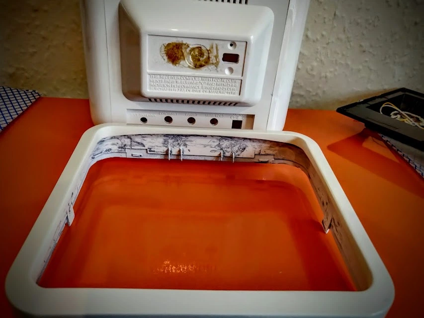
I gave it a basic wipe over, sandwiched it in paper towels and put it aside to have a good weep (The screen, not me!) and got back on with the shell.
I filed ports out of a white piece of plastic and glued it inside the shell. It’s functional but I know it could look better, that was a problem for another day.
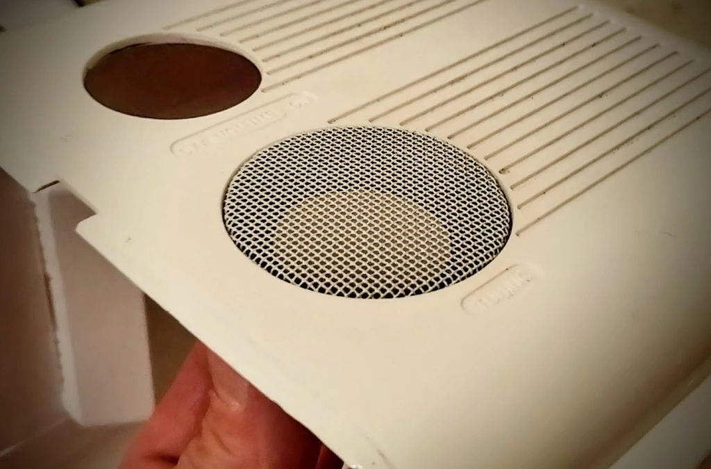
I also cut holes for the speakers either side. It will make for great stereo separation. I also hammered out the speaker grilles with my usual level of finesse. 🙂
In case anyone wondered how I meticulously and carefully hand craft the bespoke speaker grilles for my current project, I have a short tutorial… 😂 pic.twitter.com/q7YepZ7VQZ
They ended up fitting really well but I’d prefer a different mesh, another job for later. 🙂
For the controls, I’ll use the existing volume button but as a d-pad and I added a small, aluminium button for the power. It’s the best use of space I can think of and feels quite nice to use.
I’ll solder lines from the original button matrix on the display when it’s ready to assemble, it certainly doesn’t look out of place! 🙂
This is it for part 2, I’m really behind on this blog and lots of progress has been made since despite me having the daft idea of changing the spell half way through but that’ll be covered in the next part.
If, for some unfathomable reason, you absolutely can’t wait then I generally post on Twitter as I go through a project. It’s quick and easy and doesn’t break my flow, you can see where I’m at right now here:
I’m a glutton for punishment and have decided to upscale my existing FatScreen mod idea. The last time it took 27 attempts to get right, I’m hoping it’ll be easier this time (He said confidently!)
I’m using an 8″ IPS screen and a Portavision 7″ I scored last second for cheap on eBay and plan to combine them into something with a lovely curved screen.
The screen I’m using doesn’t have RGB in so I’ll use a GBS 8200 board modded with GBSControl, the original units are a bit pants but with the GBSControl mod, they’re pretty good.
Lots of Project bits!
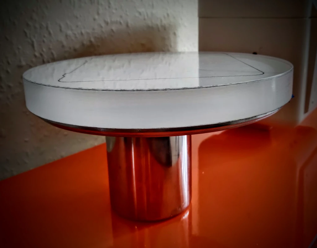
To upscale this, I needed to make a lens that is way bigger than I have ever made before, I always try to do the hardest part of any project first and the lens is very definitely the hardest part!
I’ve used a decent chunk of Perspex for this which I needed to cut and shape into a lens, this is A) Difficult. and B) Disaster prone. Perspex is a moody beast but if I can get the lens made, I’m over one of the hardest parts!
250 x 250 x 25 – That’s big!
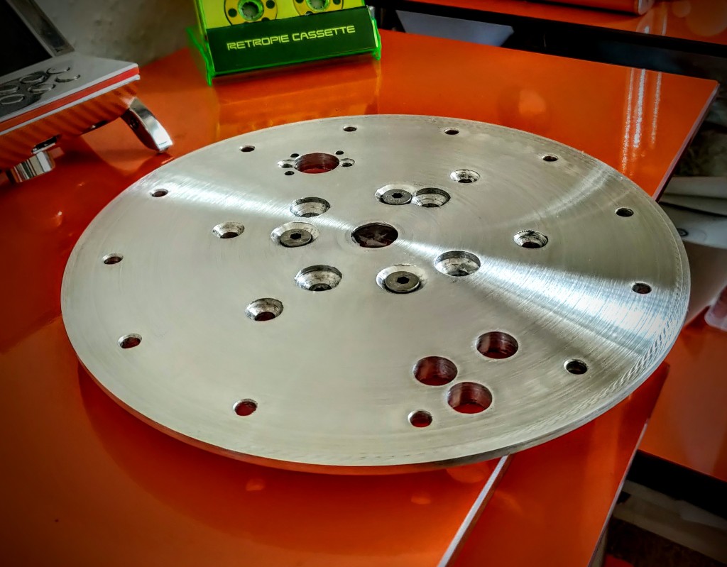
I’ve made a large arbour to bond the Perspex to for machining as there’s no other way to put it onto my lathe.
Well that’s a honking great arbour!
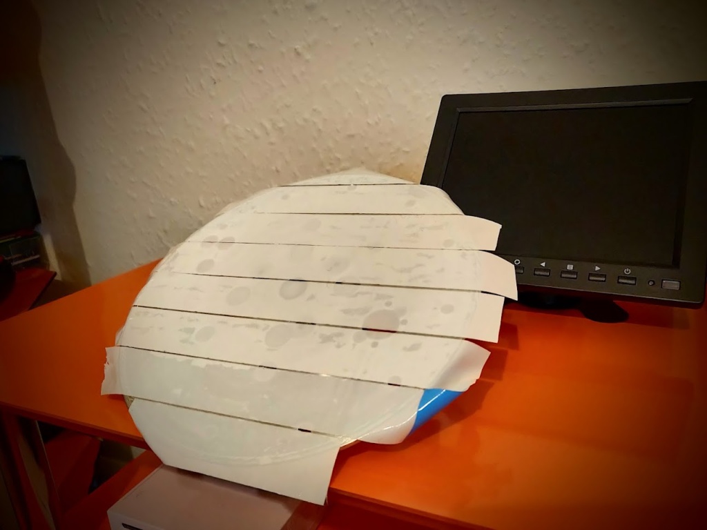
I’ll use double sided thermal tape to hold it onto the arbour, it won’t come off in a hurry and may not even come off when I need it to!
Mmmmm… Sticky! 🙂
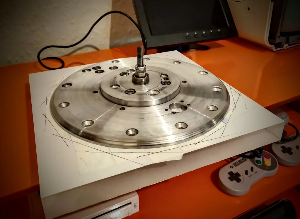
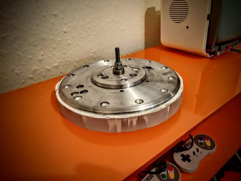
I’ve designed the arbour to spin on a shaft, this’ll help with final shaping of the lens on a ‘slightly modified’ Belt sander.
So very big!!
I’ve roughly cut the shape out before putting it in the lathe, knocking those corners off is likely to go Donkdonkdonkdonkdonkcrack!
The roughest of rough cuts
It was tense turning the lathe on with this in place for the first time, so much scope for disaster! I got it rounded off nicely though.
Round!
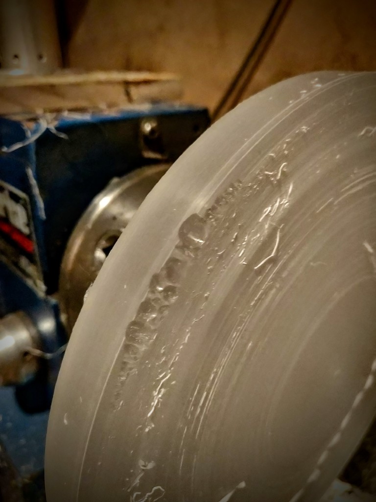
I gave the lens a rough shaping to map out the curve next. My lathe tools are for metal so it’s hard going. I tried something new, and thought I’d try it by hand with a chisel, I now know this to have been a monumentally stupid idea.
It was all going well until ‘something’ caught. It all happened so quickly that I still don’t know what went wrong. At the time, I slapped the shut off switch for the lathe really quickly as my hand got dragged in too.
I sat in shock, holding my hand which hurt like buggery. I was holding one hand in the other and eventually took a quick peek at my hand to inspect the damage (A bit of a Schrodinger’s injury, I couldn’t tell if I was injured until I looked)
Luckily my hands are quite bendy so I got away with some scrapes and bruising. It was definitely a warning to be more careful (and less of an idiot!)
FUUUUUUUUUUUUUUUUUU!
Thankfully, the Perspex was way oversized so it was recoverable – Phew!
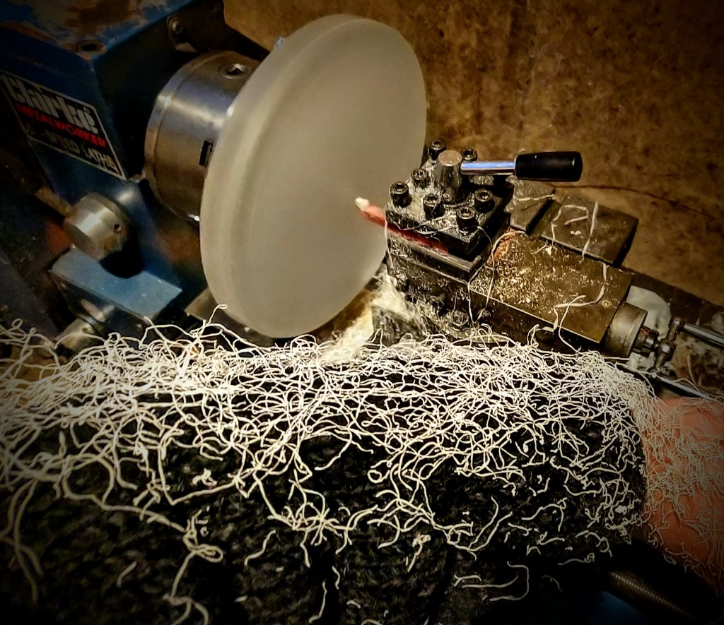
The lathe tool needed to go, it started smooshing the plastic down onto the piece instead of cutting it and was taking forever.
‘A bit’ messy…
I ground a tool specifically for Perspex out of an old knackered bit, Much better! I can start making some serious progress! Having just X and Y to work with is a bit like drawing a circle with an Etch-a-Sketch but doable!
New tool – faster (and safer) progress!
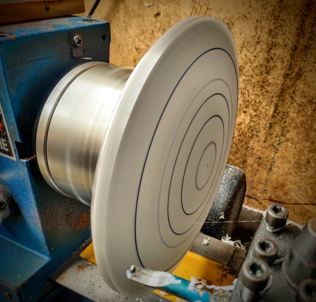
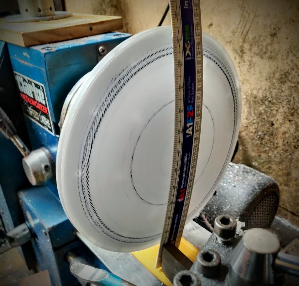
To finish the rough curve, I used a bendy ruler and rubbed it against the Perspex to get the right shape, it marked the high spots nicely. It took a few goes at marking, then machining off the high spots but the shape was getting there.
Bendy ruler FTW!
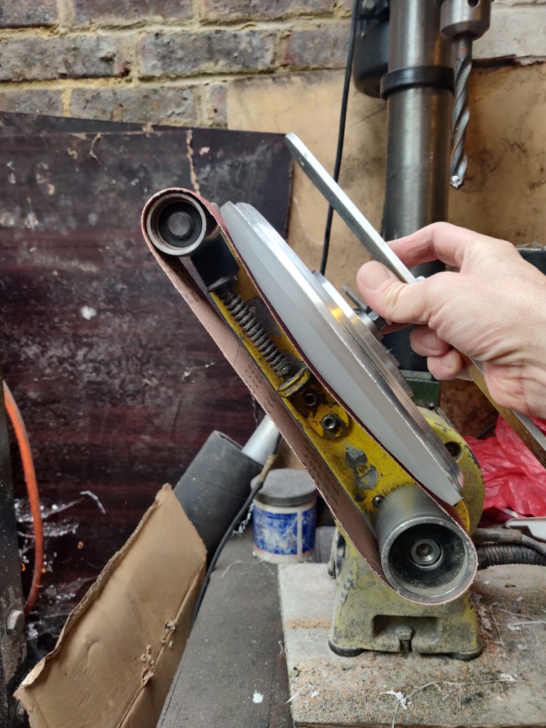
I took the platen out of my belt sander to get the curve I needed, it worked so well that I had the right shape in just under an hour.
Not pretty but definitely functional
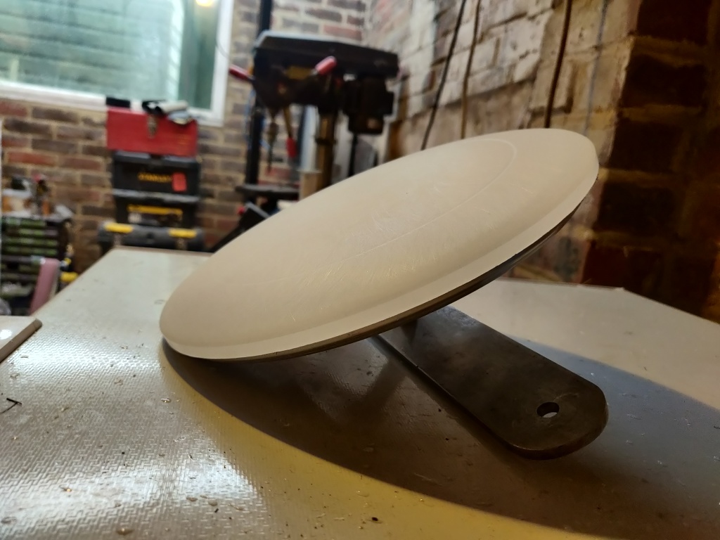
After belt sanding, I got a lovely curve!
Curvaceous!
I needed to check the geometry so gave it a quick buff, it turned out perfectly!
Nice!
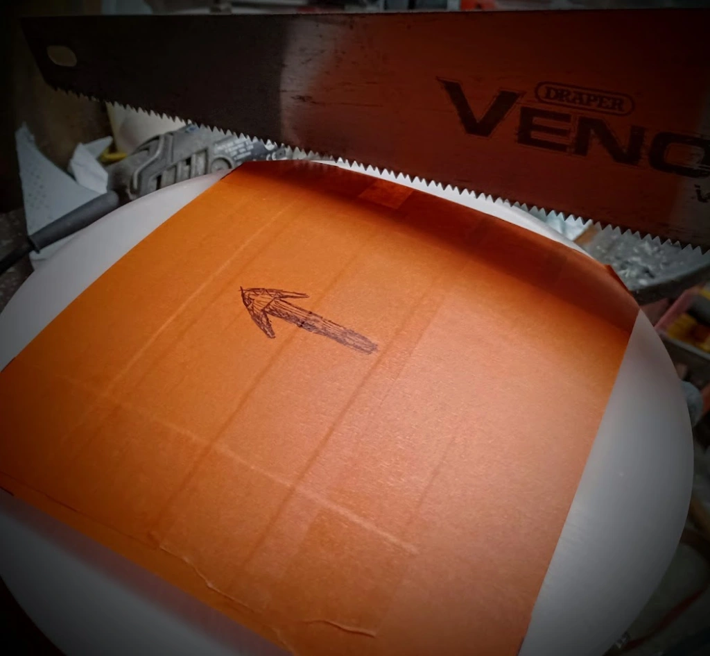
Now the geometry was right, I needed to cut and shape the lens to the shell. Yes, that’s a wood saw!
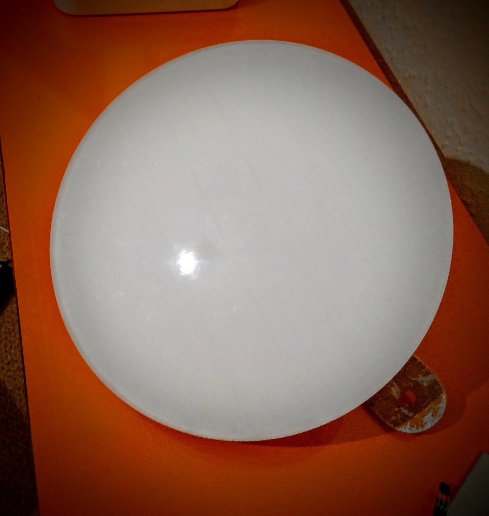
The lens is roughly cut and shaped but needs a final fettle and polish. It’s a little oversized but it’ll shrink after final sanding and polishing.
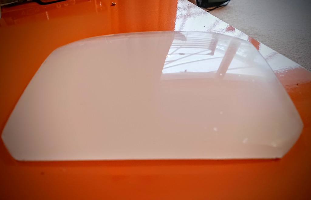
Final polish done, lens complete!
Hah! Lovely!
In the next part, I’ll be prepping the shell and crafting a new Bezel. I still don’t know if any of this will work as intended but I’m going to push on and find out. 🙂
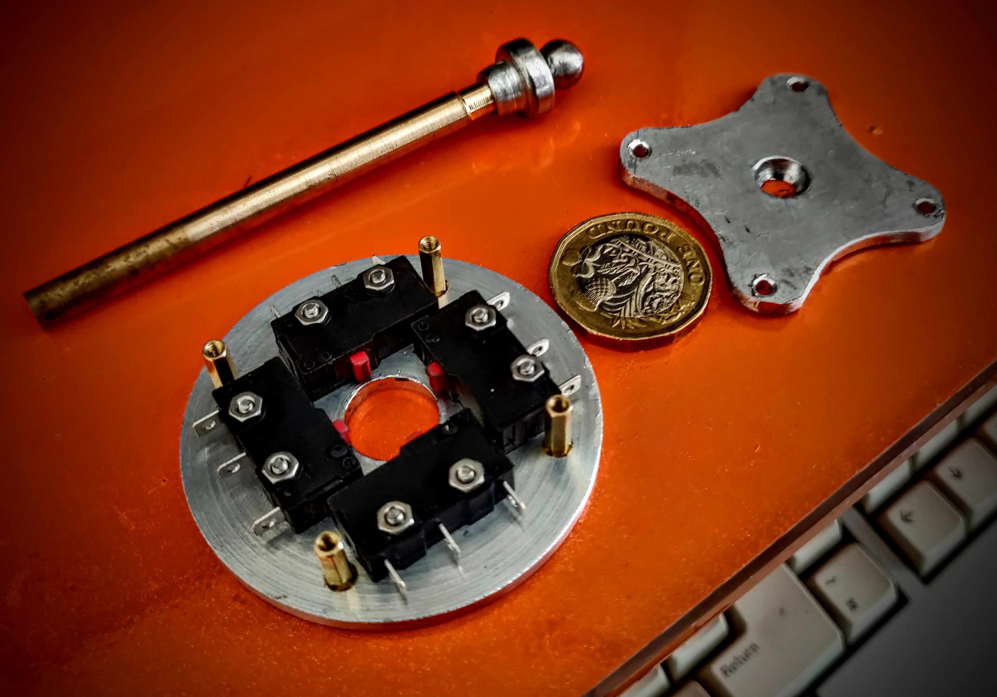
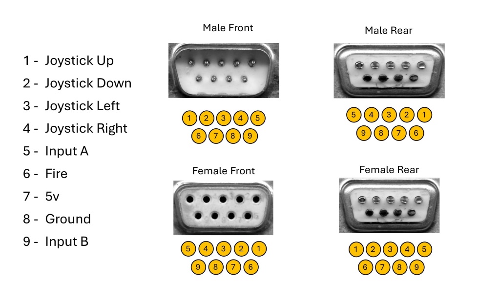
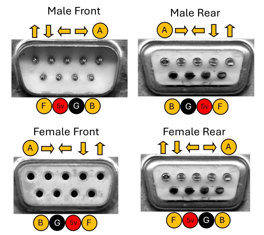
I have been playing around with making a joystick mech lately as traditional mechs are too large to put them where I want to. I started designing my own using smaller Microswitches.
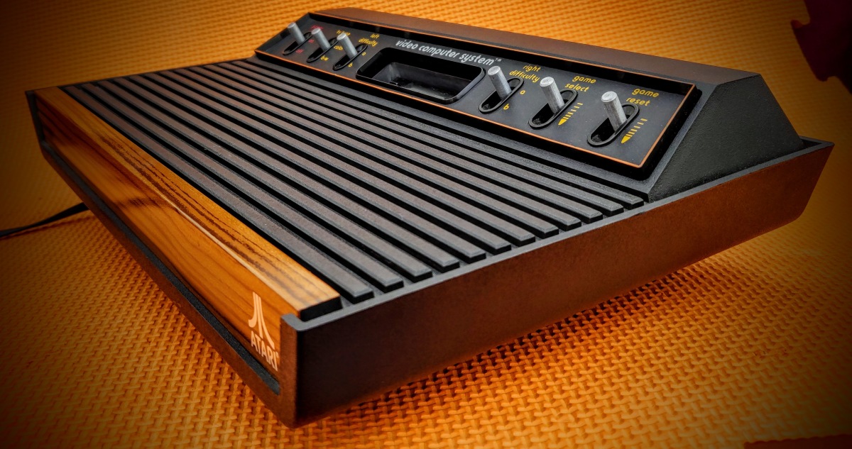
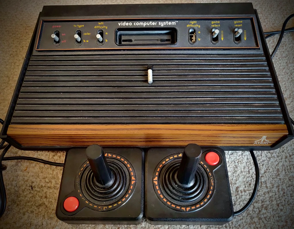
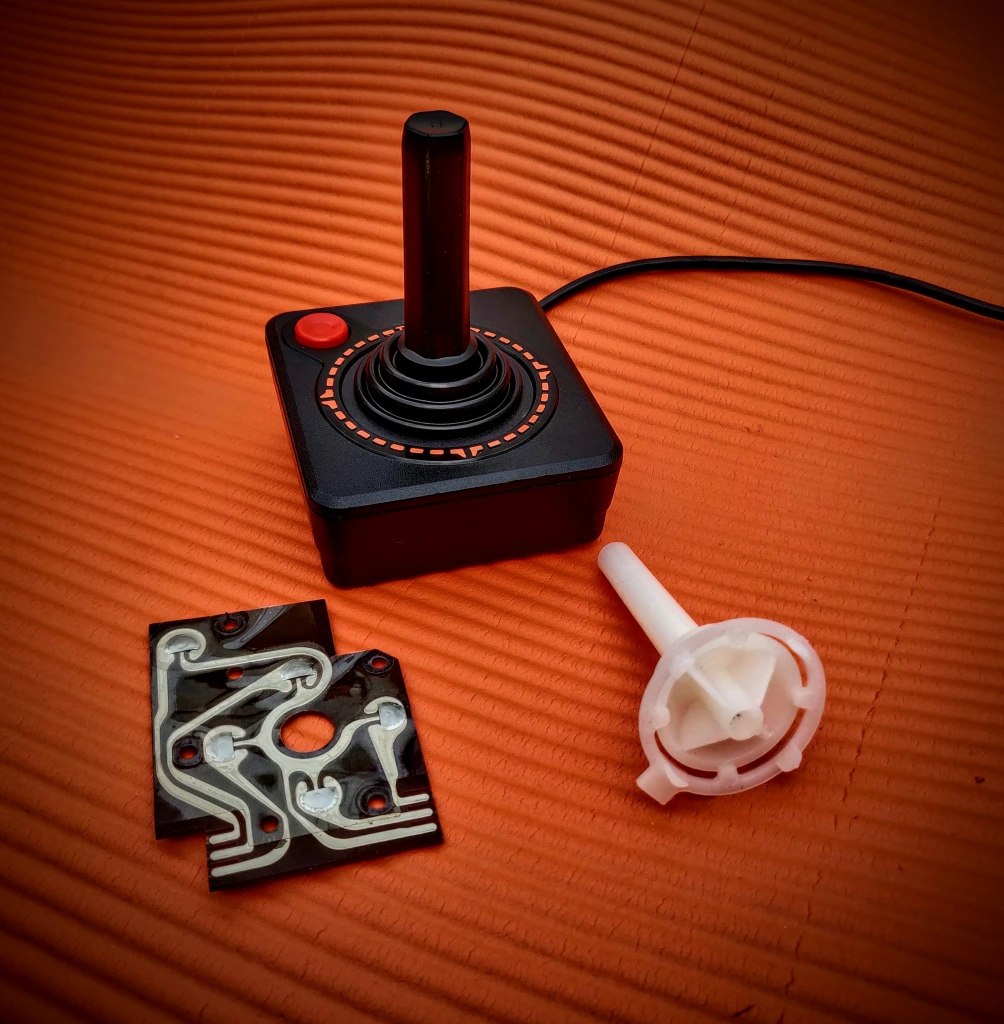
After a few revisions I got a working prototype up and running and realised it would fit nicely into an Atari 2600 joystick, I had to give it a go…
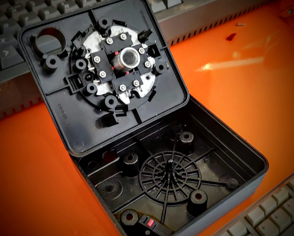
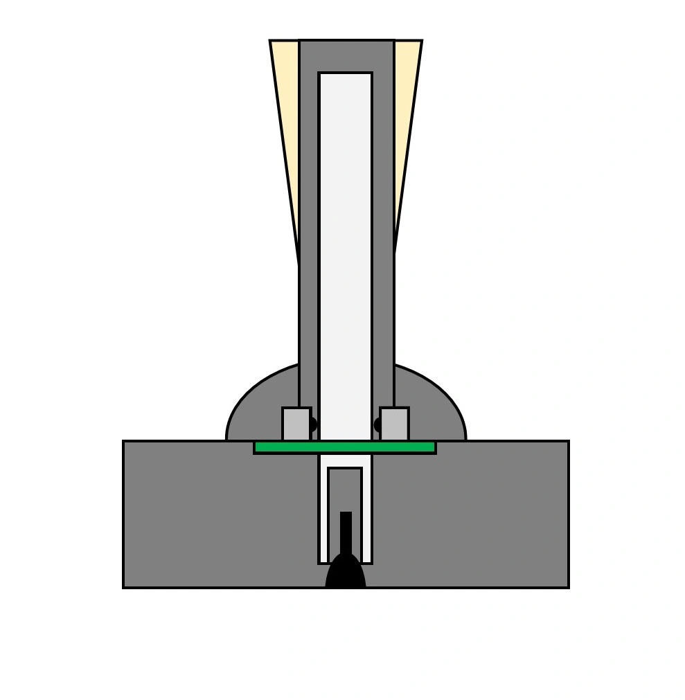
After a bunch of fettling, I got a mechanism fitted. There are loads of support struts in the Atari joystick so working round those was an issue. The idea is that a hollow tube acts as a pivot point at the bottom and the switches are directly in contact with the shaft of the joystick.
I got it assembled and gave it a go… It was AWFUL!!! Everything a joystick shouldn’t be. Too much travel, poor diagonals, sloppy, poor centering. Terrible.
I have 6 Atari sticks, and I upgraded 4 of them in the past, when tweaking them, I play them off against each other and see which ones are ‘best’. This stick was second worst. Despite being machined to fractions of a millimeter, it was entirely disappointing. My other refurbs worked great.
The main issue is the microswitches, the return spring force isn’t even across the range of travel, and only pushes back fully when it is past the halfway point. If the mechanism was made tighter it actually made it worse.
I decided to use a similar approach to the one I used when I built a bartop. It used a shrunken arcade mech using tact switches and works really well.
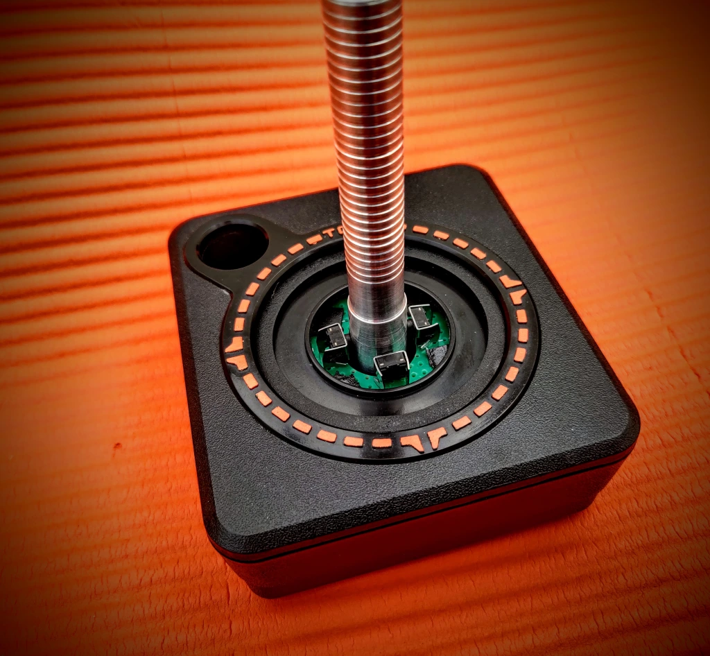
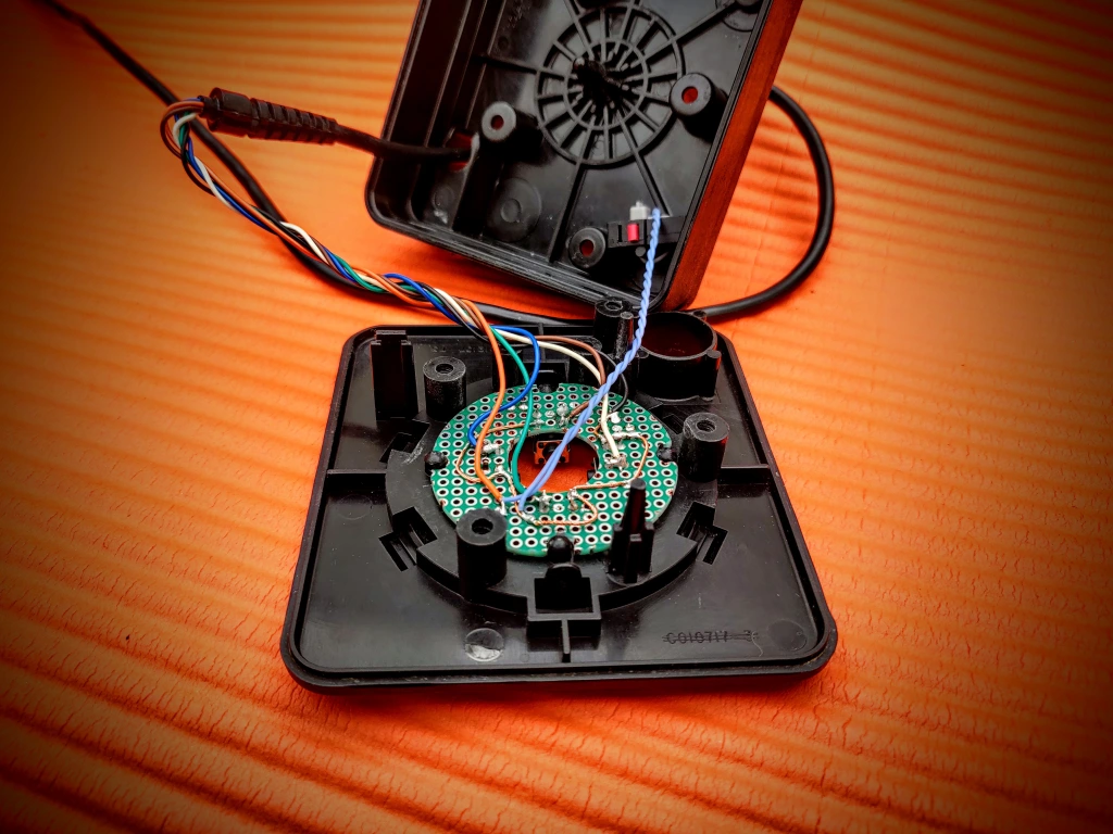
I used 4, right angled Microswitches and put them as high as I could, the further the distance between the switches and the pivots, the smaller the travel will need to be. I managed to get them to fit nicely inside the rubber boot.
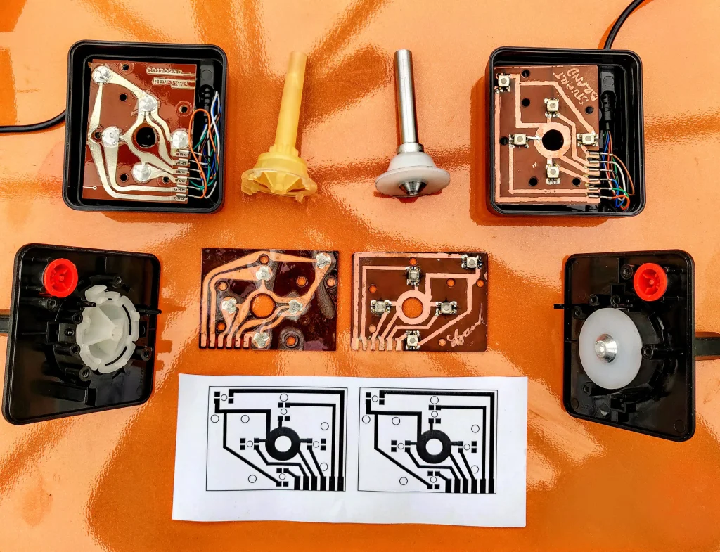
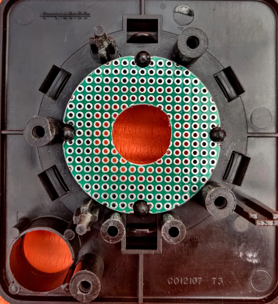
I cut a PCB to fit in the very top of the joystick. I filed out sections of the PCB where the lugs are so that it located nicely and snapped in like lego.
I then mounted 4, right angled switches in the board so that they line up exactly with the joystick shaft. The shaft is 12mm where it goes into the rubber boot and 13mm where it touches the actuator. There’s a little wiggle room in the switches so that adjustments can be made before soldering.
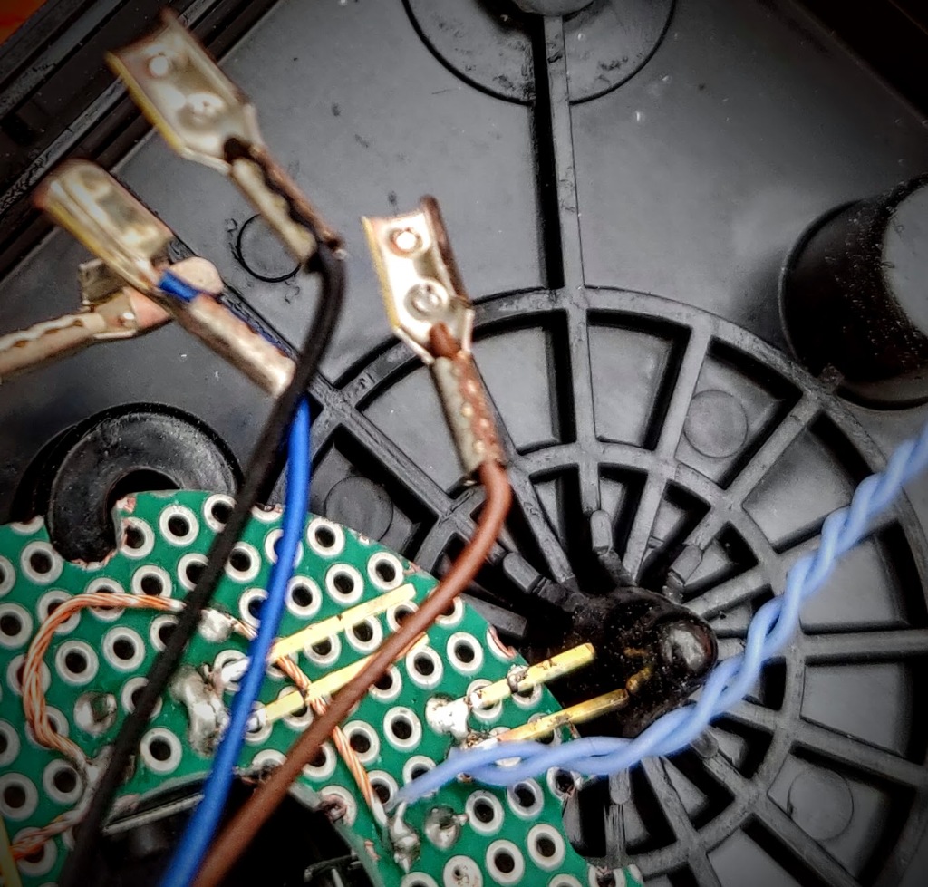
The connectors on my Atari joystick lead were really brittle so I had to solder them directly to the board which was disappointing as I was hoping to use spade connectors on the mechanism to attach them and not have to chop the cable. I’ll get some spade connectors and fix it later.
Once it was soldered, I fixed the PCB in place with some really strong double sided tape. The board is held in really securely by the lugs so it’s just to hold it in place.
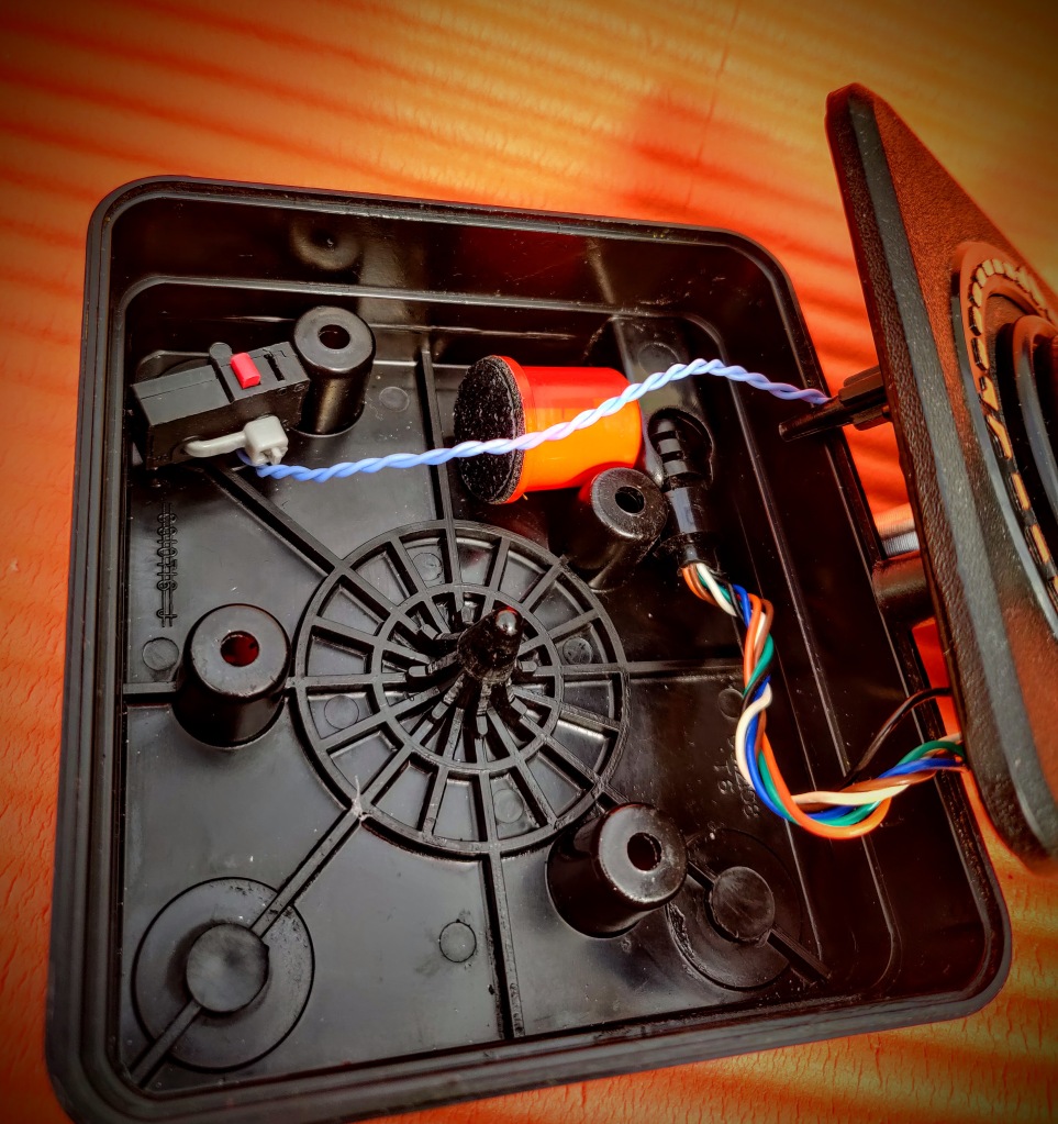
I added a fire button using a standard microswitch. The support post is slightly off center so I used this to cable tie the switch in place. I taped a piece of plastic over the bottom of the fire button so that it made good contact with the switches actuator and was at the right height.
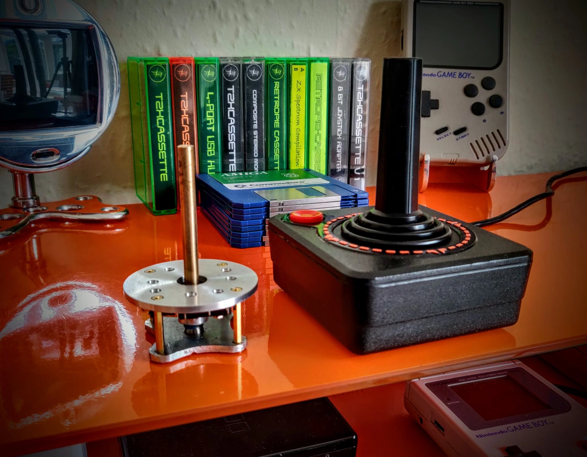
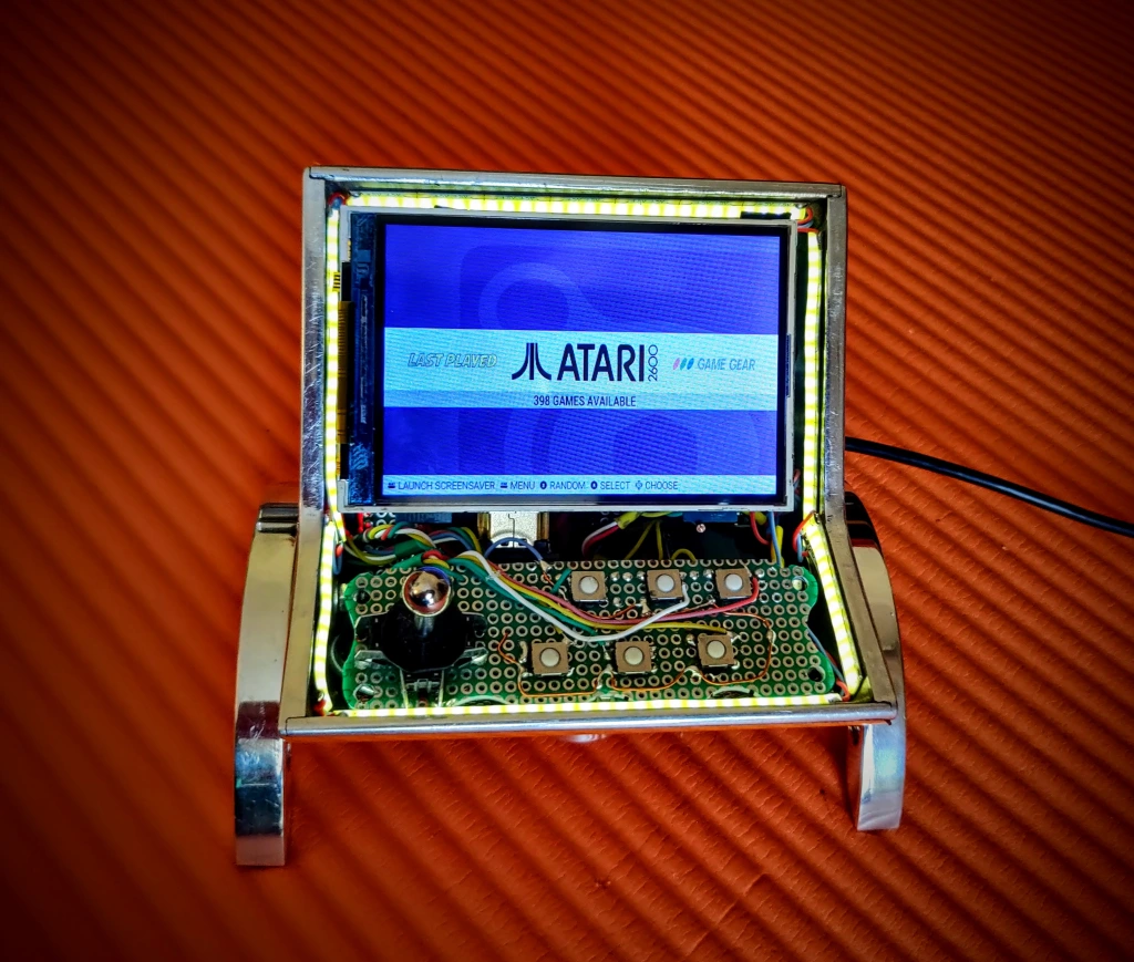
I put it together and tested it without the boot fitted and WOW! What a difference! Minimal travel, no excess play, solid diagonals, perfect!! 😍
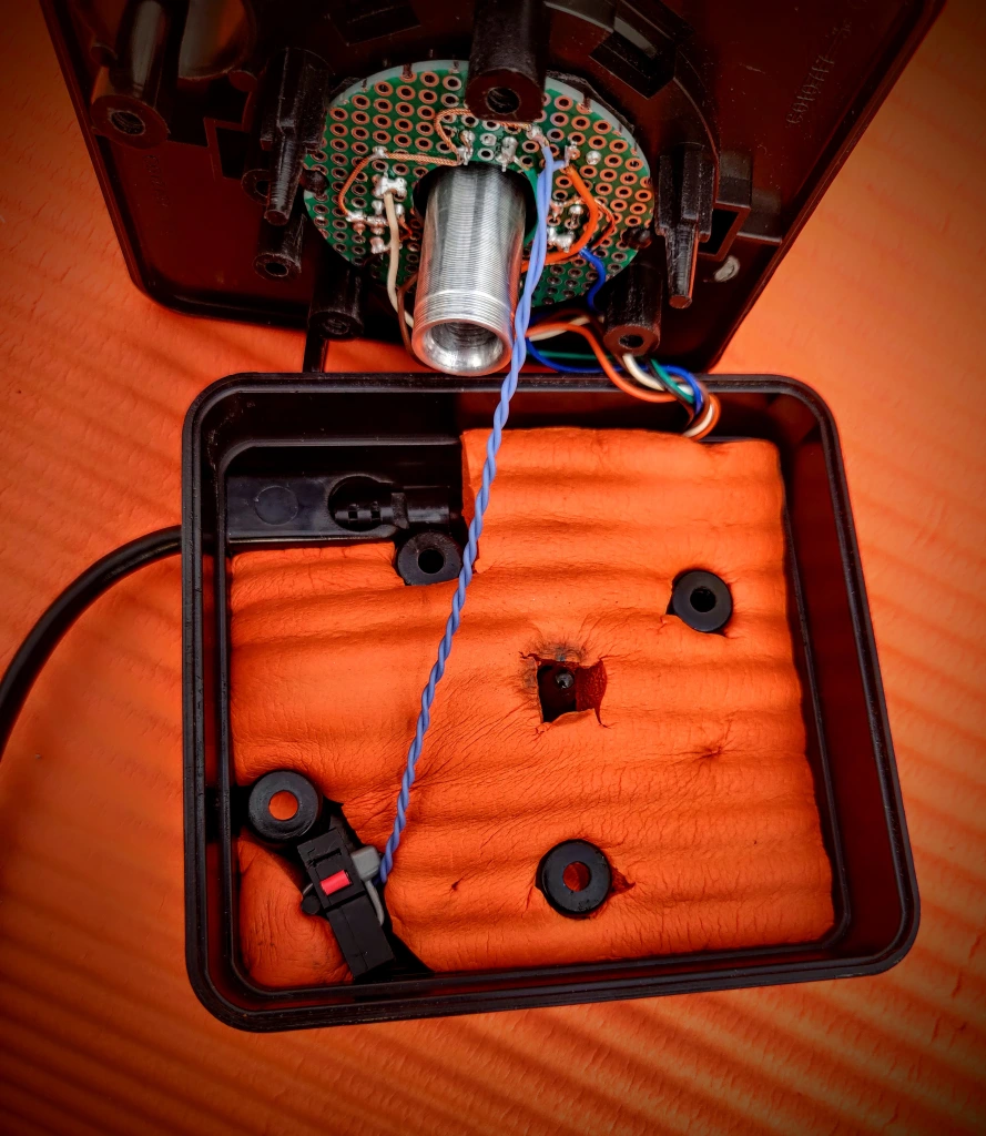
I re-fitted the rubber boot, this holds the joystick shaft down and in place, I also added a foam layer at the bottom for sound insulation as the shell is really empty.
I screwed it back together and it works perfectly! It is way better than my other modded sticks and has now been promoted to my best stick! It it definitely worth doing and it is non destructive and completely reversible!
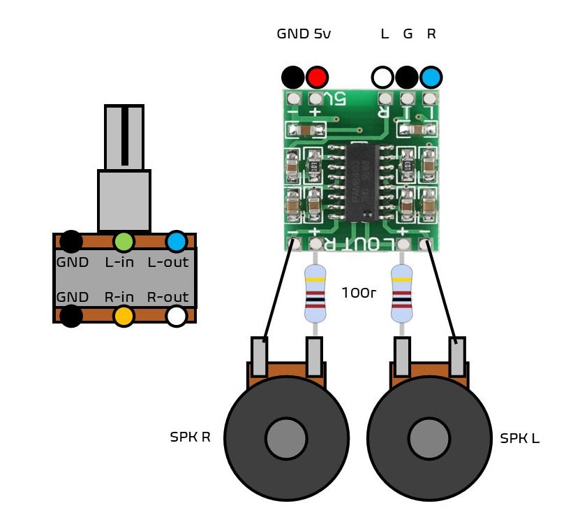
I couldn’t find any clear guides for wiring an ‘old school’ 6 terminal audio potentiometer, this may help someone.
The resistors are there because there’s a small noise issue with the Raspberry Pi. This noise is constant, no matter what the volume is set to and is always there. It also gets significantly worse if there’s a ground loop.
To counter this, use amixer to turn the Pi volume up to full on the Pi, and put a 100r resistor in line with the speakers. This out shouts the background noise and is attenuated later when it gets to the speakers.
To use a clumsy metaphor, It’s like having a whistling nostril and screaming into a cushion.