

Hi, this is an update to: Cassette Adapters on the ZX Spectrum 128k +2 don’t work. Or do they?
Hi, I’ve been faffing with the TZXCassette and I never could get Head over Heels to run properly. I would like to make the Cassette as device agnostic as possible and this means that the filtering had to go.
To save space, instead of a full sized Cassette head to send the signal to the Speccy tape head I used a 10mh inductor, a coil is a coil right? This was both an excellent and terrible decision.
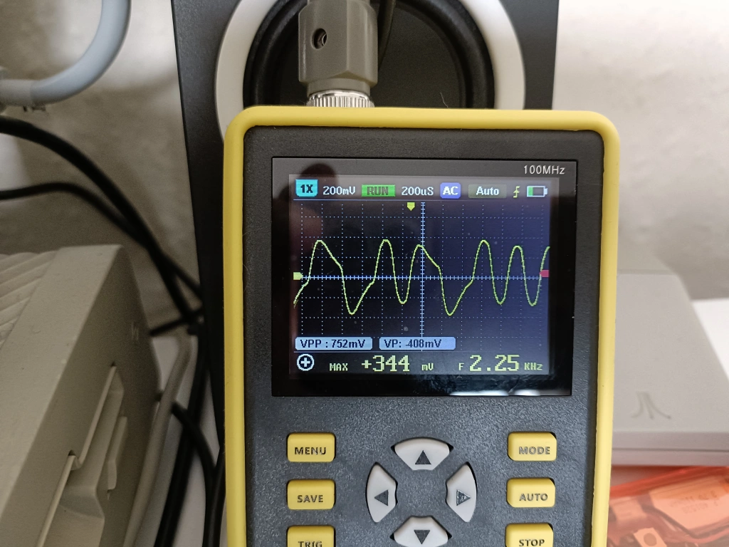
Using the inductor had plenty of volume but that distortion I had in the previous post was back, and with a vengeance! This is what the tape deck is seeing:
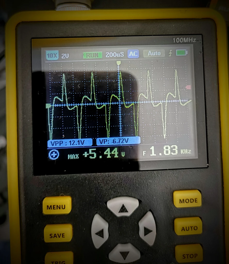
Oh wonky waveform, you appear with the tedious inevitability of an unloved season.
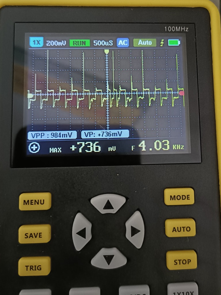
And this is monitoring the signal to the tape head.
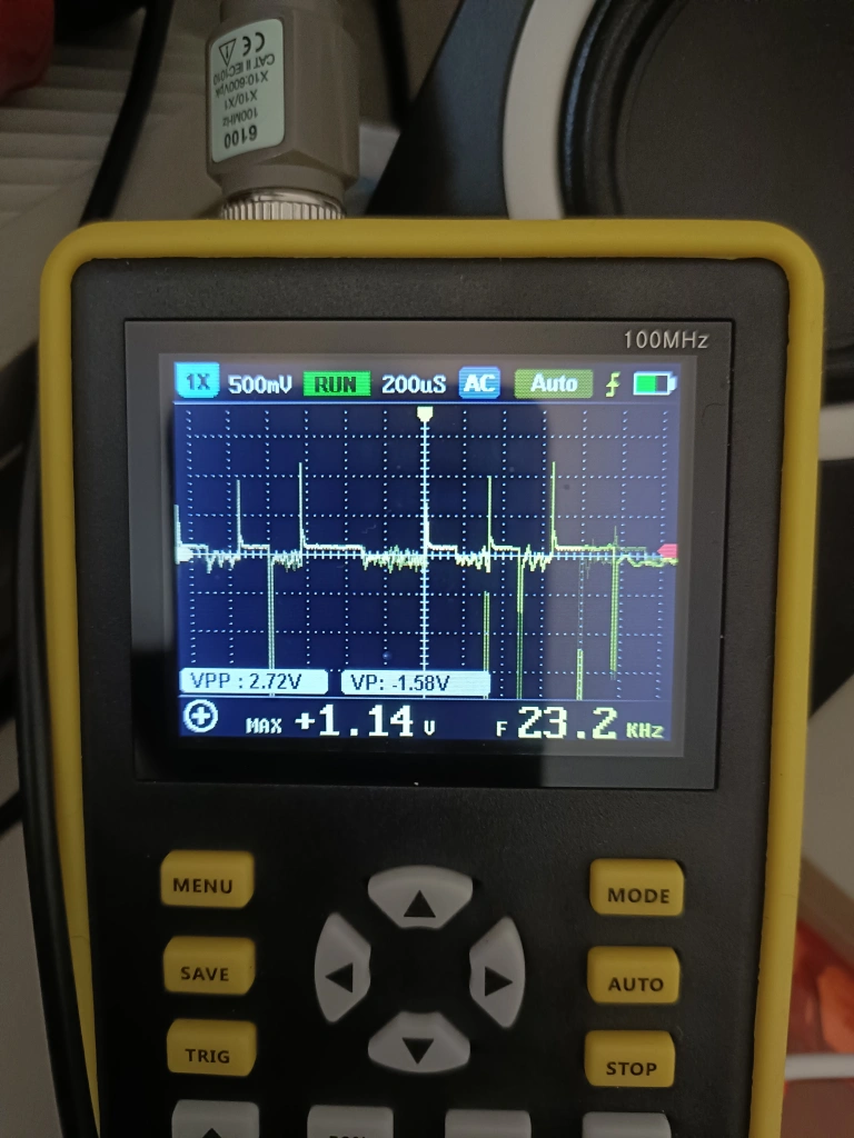
What the flip are those spikes?? I didn’t understand what was going on at all. Without the inductor, the waveform is absolutely lovely, as ideal as it gets.
Hmmm…
I’m often in a situation where I need to work out something that I have no clue about and I have a process of sorts. it involves poking at a problem until something diagnostically interesting happens, then going away and having a think about what I’ve done.
All I had by way of a problem statement was “Inductors make a big spike, it is not helping”.
I did a bunch of Googling (then switched to Ducking ‘cos Google is terrible!) then I made myself an impressive array of high pass, low pass, band pass filters and poked at it for about a week without much of a change.
I noticed something weird. When I had filters applied, I got some improvement but nothing was working as I would expect. I tried putting a variable resistor in line and adjusting it but I was getting a low pass filtering effect which shouldn’t happen.
I decided to read up on inductance in more depth and that’s when I realised what was happening. Short version: An inductor’s gonna induct.
Long version (buckle up!)
The voltage is being applied to the inductor, the inductor then generates a magnetic field. The problem happens when you switch the current off, the field in the coil collapses and the flux has to go somewhere. It gets converted back to electricity, and dumped back into the system, creating a massive voltage spike.
(which is why the resistor worked like a low pass filter, because it was!)
It turns out that if you’re stupid enough to put 5 volts into an inductor and rapidly switch the power on and off, the inductor will charge like a capacitor. Depending on the pattern of short and long spikes, it would charge to a greater or lesser degree.
I now knew I was looking at an inductance spike and apparently, the way to fix it is to put a flyback diode in. I knew nothing about diodes other than they’re ‘one way valves’ and after a bit of research, settled on a 1N5817 Schottky diode and put it in parallel.
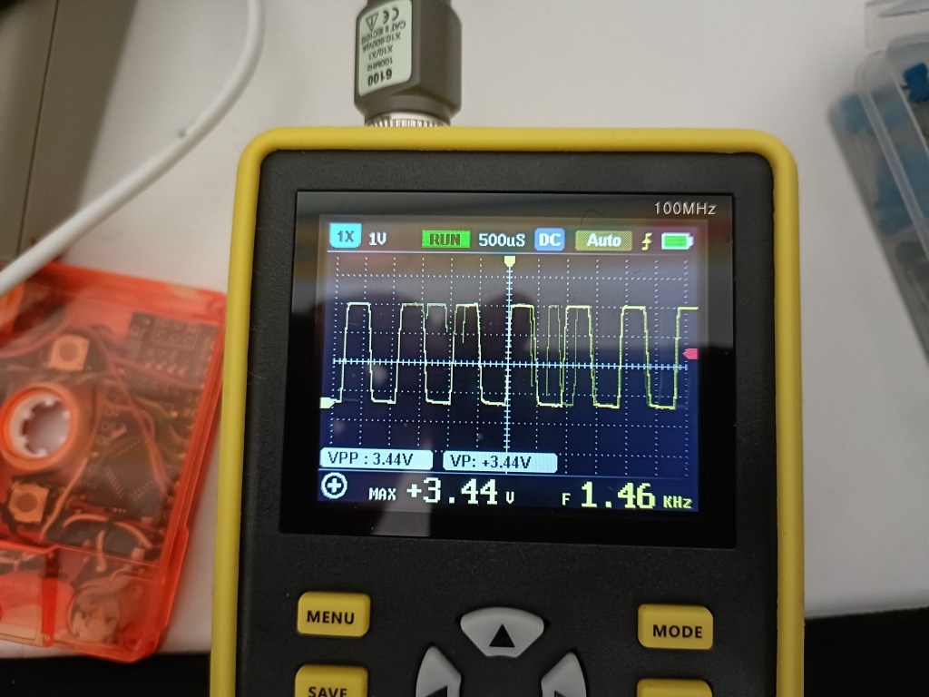
It was immediately better! Still some spikes but nothing too terrible. I filtered it, and got to a smooth waveform.
I set about testing games and got to a sticking point. I could load everything except for Gilligan’s Gold (with a 33uf cap across the inductor) or load Gilligan’s Gold or nothing else (with a 220uf cap). Something still wasn’t right.
A Speccy will determine a long or short pulse by checking the distance betwen the crossover points (I think) and filtering subtly changes this to the point where some speedloaders will not work. Those remaining spikes needed to be squished, but how?
The current was being blocked from being reverse dumped back into the circuit by the diode but it had nowhere to go and was still making those spikes. Just for laughs, I put an original cassette head on and tried it.
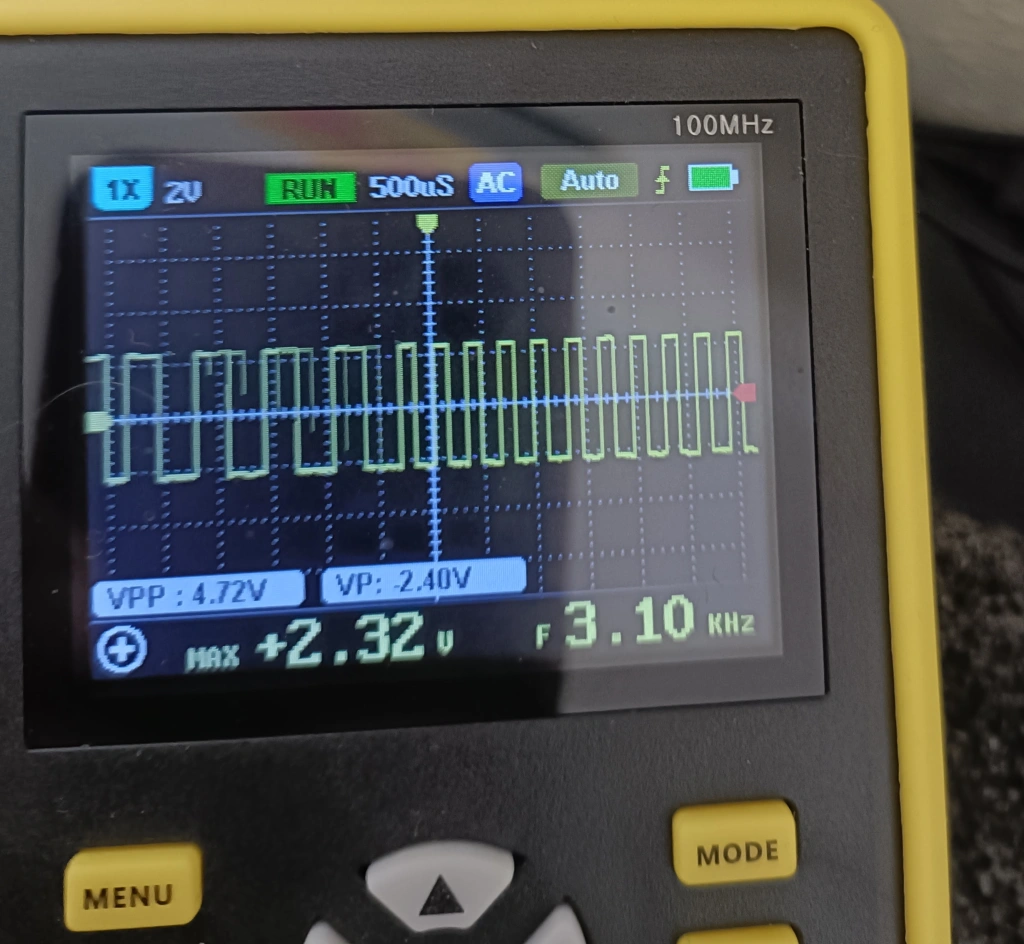
It was perfect! Still a little shimmy on the tops of the waveforms but those verticals are super crisp. This is because the tape head has a resistance of 220Ohms and is dissipating the energy that would normally bounce around ruining my day. 🙂
Absolutely everything loads now with freakish reliability and all it took was a 2p diode!
This means I can continue my TZXCassette v3, the idea is to get it working on as many systems as possible and an unfettered signal will help massively. It would be like whack a mole otherwise, a tweak for one system would knacker another.
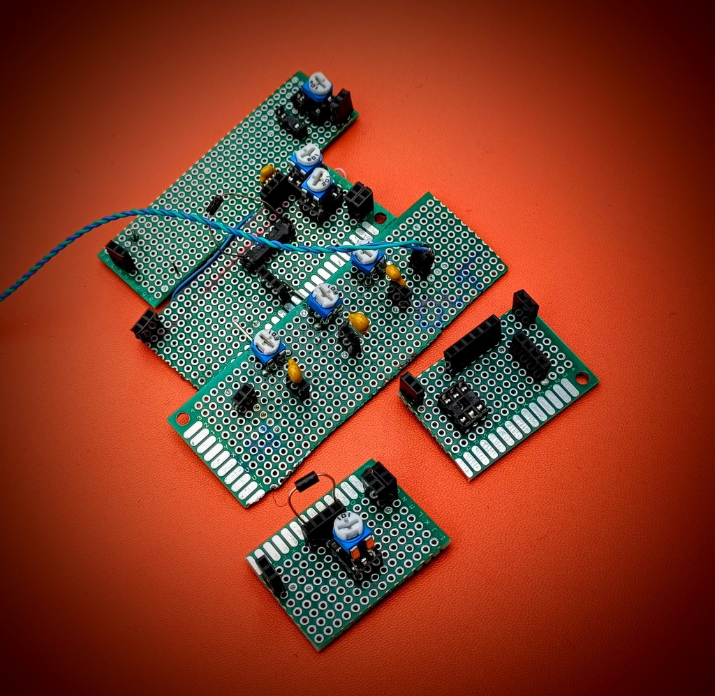
A special thanks to my Stunt Speccy. It was cobbled together from bits and has taken a real hammering for years. it is currently lidless on my test bench.
When I’m done with this project I might get it something nice. 🙂


I always feel like I’m not quite able to keep up! 🙂 So, part 1 showed ringing on the outputs (without cap), which I assume was using the cassette head. (and at the end of part 2, you’re using the cassette head, again). So it feels like I should be comparing those two graphs – the ringing output at part 1, and the last clean squarewave screenshot in part 2. If the only difference is the introduction of one diode, then how does that prevent both the ringing below zero AND the ringing above 5v (or whatever your logic-1 output is). When switching from 5v to 0v, I can see how it would overshoot below 0v, and the diode protects that, but I can’t understand how the diode protects overshooting above 5v when switching from 0v to 5v. I’d expect to see some more ringing above logic-1 level still. Or did something else change between part 1 and part 2 to counteract that?
LikeLike
Hi, it’s all very confusing and I’ll freely admit that I don’t know what I’m doing – The ringing was with the inductor I used and voltage was bouncing around all over the place and as far as I can work out, switching to a standard head with 200ohm resistance makes the energy bounce round the head and the resiostance squishes the ringing – I’ll freely admit that’s proabably wrong but I’m not going to argue with the results. 🙂
LikeLike
I *think* that makes sense (for the comparison between head and inductor), but I can’t understand what part the diode plays. I’ve tried to reproduce something similar but I don’t get the same result you get (using a cassette head with, or without, a diode doesn’t seem to make much difference). So maybe I’m just not doing the same thing as you – do you have a simple circuit diagram of the relevant bit of the circuit with/without diode?
LikeLike
I tend to be a little too fast and loose to document it but if it helps, I used a 1N5817 straight across the + and – of the sending head – if you don’t get any results, try the diode the other way round. 🙂
LikeLike